
Automatic antenna orientation and stabilization system and method

a technology of automatic positioning and stabilization system, applied in the field of automatic positioning and stabilization of antennas, can solve the problems of uncertain dangers, low or no ability of fishermen at sea to communicate with one another, and the equipment and techniques for achieving such secure communication are quite expensive, and achieve the effect of maximizing signal strength

Active Publication Date: 2019-10-15
AMRITA VISHWA VIDYAPEETHAM
View PDF1 Cites 0 Cited by
  • Summary
  • Abstract
  • Description
  • Claims
  • Application Information

AI Technical Summary

Benefits of technology

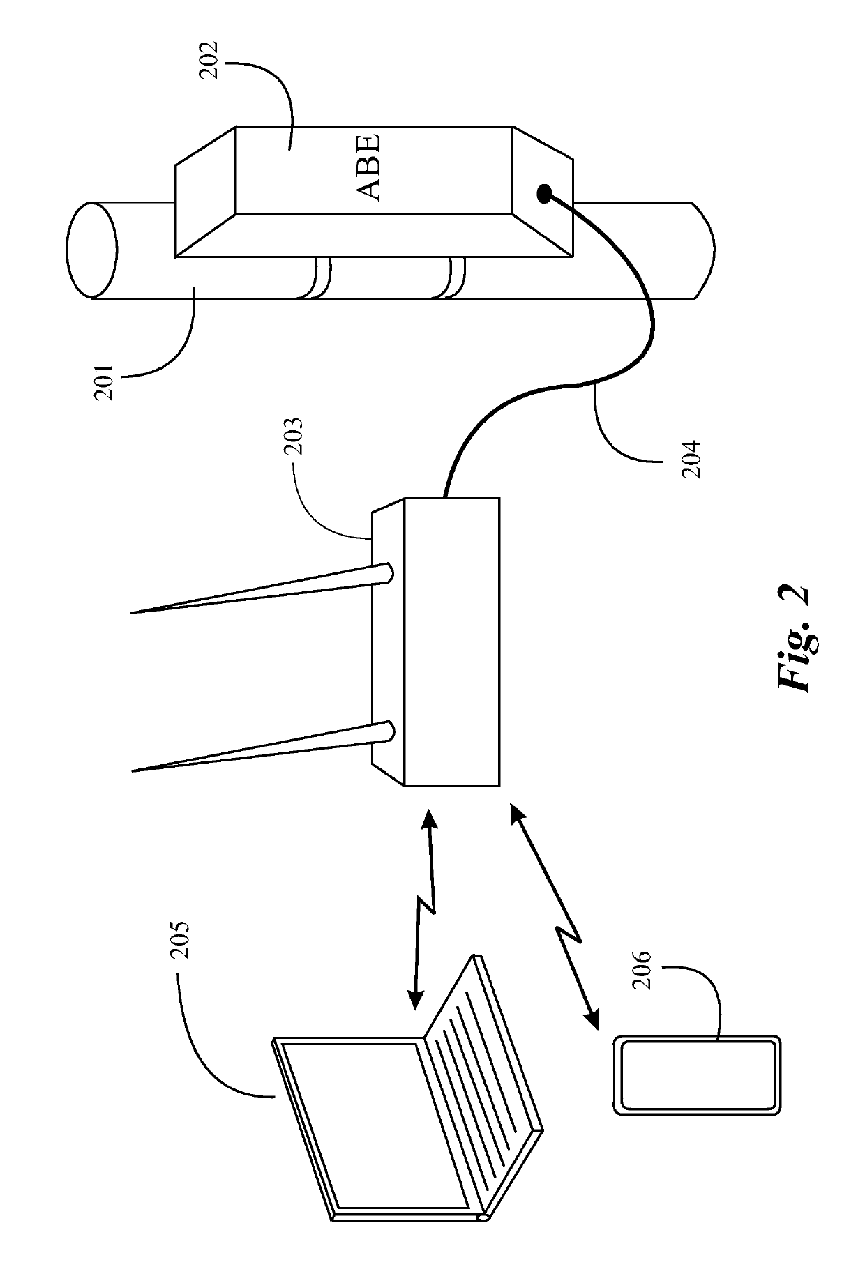
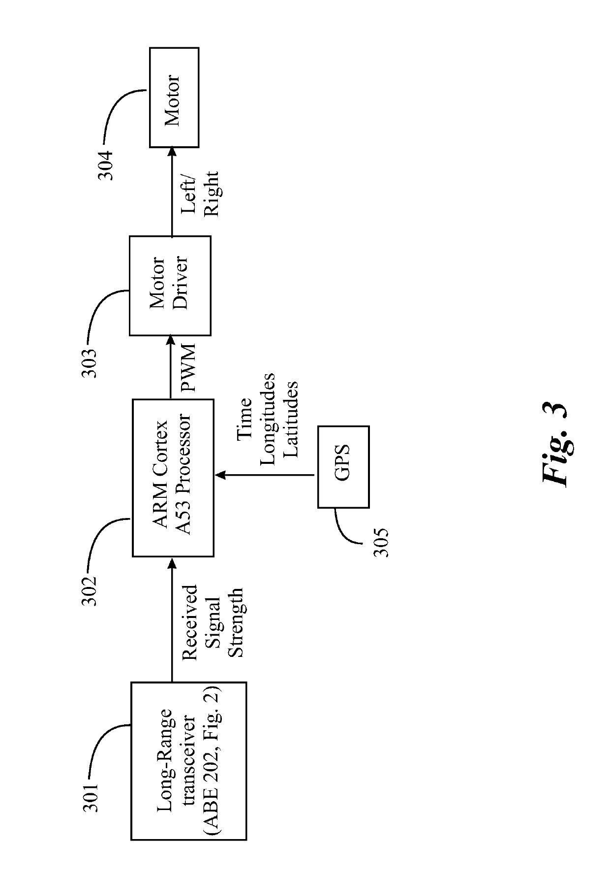
The present invention provides a method and system for maximizing signal strength between a land-based or moving first station and a second, moving station on a sea-going vessel. This is achieved by mounting an antenna on a structure that is rotatable about a vertical axis by a mechanism powered by an electric motor. The system includes control circuitry at the second station having a processor coupled to drive circuitry coupled to the electric motor, which initiates data communication between the second and the first stations, determines signal strength, and causes the antenna to rotate by driving the electric motor, maximizing the signal strength. The technical effects of the invention include improved signal quality and reliable communication between the two stations regardless of their relative movement.

Problems solved by technology

In this activity there are certain dangers, which may come about because of a variety of reasons, such as equipment malfunctions or sometimes unexpected severe weather.
Further, in many circumstances there is little or no ability for fishermen at sea to communicate with one another to coordinate activity, or to keep in touch with family at home, on land.
It is well-known, however, that equipment and techniques to accomplish such secure communication is quite expensive, and in many cases beyond the financial capability of owners of such vessels, and also of government agencies that have an interest in providing safety services.

Method used


Image

  • Automatic antenna orientation and stabilization system and method
  • Automatic antenna orientation and stabilization system and method
  • Automatic antenna orientation and stabilization system and method

Examples


Embodiment Construction

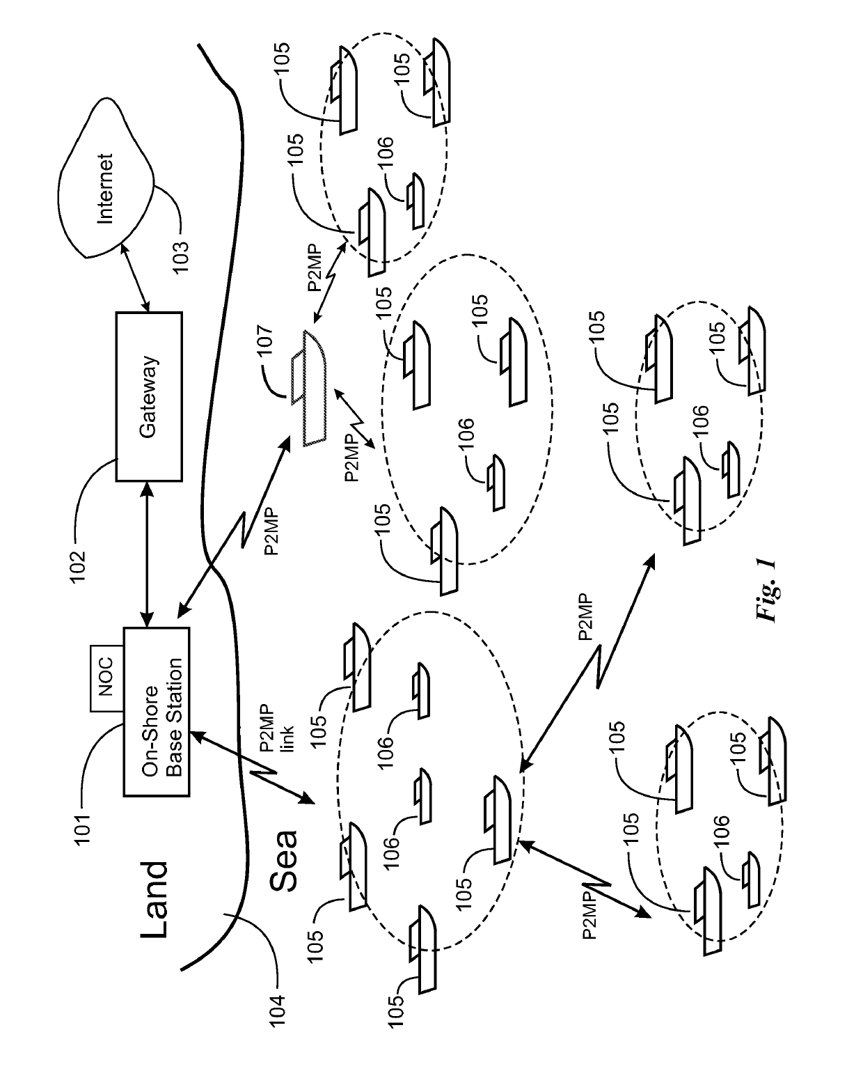
[0018]In various embodiments and implementations of the invention described in specific examples below, with reference to figures filed with this application, a wireless communication system is provided as an effective and reliable way for fishermen to communicate amongst themselves and with the shore during emergencies and other times using text or email messages and voice calls. Video may also be supported. In various embodiments the system caters to near-shore circumstances, described as within 46 km, and also in other embodiments to groups of fishing boats at significantly greater separation from the shore.

[0019]There are a number of factors that contribute to the problem, which, of course, influence the nature of the system that solves the problem in different embodiments. These factors include:[0020]Extreme mobility: Boats are free to move anywhere at any speed they can muster as opposed to constraints imposed on vehicles on a road.[0021]Variation in density: Concentration of ...


PUM


Abstract

A method for maximizing signal strength between a land-based or moving first station and a second, moving station on a sea-going vessel is provided, comprising mounting an antenna on a structure on the moving station, the structure rotatable about a vertical axis by a mechanism powered by an electric motor, initiating a data connection between the first and the second stations by a processor in communication circuitry at the second station, reading a received signal-strength by the processor, and operating the electric motor by the processor, rotating the rotatable structure, maximizing the signal strength.

Description

CROSS-REFERENCE TO RELATED DOCUMENTS[0001]The present invention is a continuation-in-part to a patent application Ser. No. 15 / 076,998, filed on Mar. 22, 2016, which claims priority to Indian application 201641004600, filed Feb. 9, 2016. Disclosure of the priority documents are incorporated herein at least by reference.BACKGROUND OF THE INVENTION1. Field of the Invention[0002]The present invention is in the technical area of network communications and pertains more particularly to tracking of fishing vessels from base stations on land and facilitating communication with and between vessels.2. Description of Related Art[0003]In many countries fishing in fresh water lakes or in the open sea, often in a loosely-defined area along a shoreline, is an important economic activity, engaging a relatively large number of fishing vessels, and employing a large number of people. In this activity there are certain dangers, which may come about because of a variety of reasons, such as equipment ma...

Claims


Application Information

Patent Timeline
Patent Type & Authority Patents(United States)
IPC IPC(8): H01Q1/12H04W4/02H01Q3/04H04B7/00
Inventor RAO, SETHURAMAN N.RAMESH, MANEESHA VINODINIRANGAN, P. VENKAT
Owner AMRITA VISHWA VIDYAPEETHAM
Learn More