Method and means for detecting motor rotation

a technology of rotation detection and motor, which is applied in the direction of motor/generator/converter stopper, dynamo-electric converter control, etc., can solve the problems of increasing the load on the motor, requiring work from the motor, and external devices adding extra cost and complexity to any system in which they are installed, so as to reduce the cost, reduce the cost, and reduce the effect of external devices

Active Publication Date: 2016-04-07
FLOW CONTROL LLC
View PDF25 Cites 0 Cited by
  • Summary
  • Abstract
  • Description
  • Claims
  • Application Information

AI Technical Summary

Benefits of technology

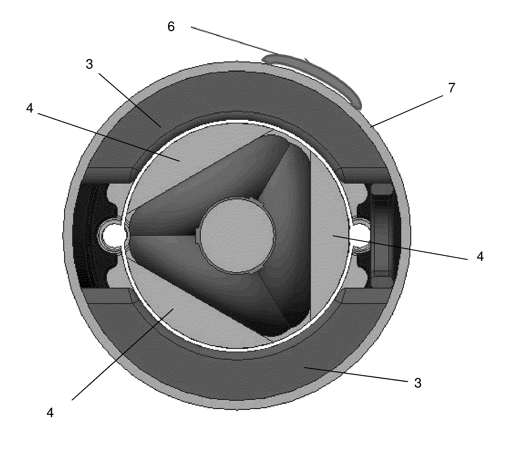
[0024]The Hall Effect Sensor may be mounted internally to the motor housing and configured to sense the magnetic field, including being mounted on an internal surface of the motor housing. By way of example, the motor housing may be configured or formed with a hole therein, and the Hall Effect sensor may be mounted internally inside the motor, including through the hole. The random noise acquired by the signal from the Hall Effect sensor may be minimized due to the motor housing acting as a protective shield, and the signal strength is maximized due to the proximity of the Hall Effect sensor with components creating the signal.
[0027]The present invention overcomes the above mentioned difficulties in the prior art device by measuring the rotation of a motor without the use of any external device mounted to the motor shaft. In addition, the system is low cost, simple, and can be incorporated into systems with limited space available.
[0028]The present invention also overcomes the difficulties of the method described in US 20130081718 A1. The method according to the present invention disclosed herein relies on measuring a change of physical properties instead of measuring their absolute value as is the case with the method outlined in US 20130081718 A1. This allows the measurement circuitry to be simpler and less susceptible to unwanted electrical noise. It also makes the system more robust to temperature change since the change in the physical properties being measured are much less dependent on temperature than the absolute physical properties being measured using the method described in US 20130081718 A1. In addition, there is no need to make drastic changes in applied voltage using the method according to the present invention disclosed herein as is otherwise required by the method in US 20130081718 A1, so that the present invention allows the motor rotation to be maintained at a more constant speed and produces a more accurate reading. In addition, the method described in US 20130081718 A1 requires the application of a pulse width modulated voltage, whereas the method according to the present invention disclosed herein can be applied regardless of the method of power application.

Problems solved by technology

One problem with the known techniques used in the above mentioned devices, is that any device which is mechanically coupled to a motor, as is the case with the dynamometer and encoder, will require work from the motor to provide its motion.
This work will increase the load on the motor.
These external devices add extra cost and complexity to any system in which they are installed.
There are also many situations in which the space requirements of the system preclude the use of any external devices mounted on the motor shaft.
It is sensitive to unwanted electrical noise, is dependent on measurements taken when the applied voltage is drastically changed, and also requires temperature correction due to the temperature dependency of the physical properties the system uses to infer motor rotation.

Method used


Image

  • Method and means for detecting motor rotation
  • Method and means for detecting motor rotation
  • Method and means for detecting motor rotation

Examples


Embodiment Construction

[0010]According to some embodiments, and by way of example, the present invention may include, or take the form of, apparatus featuring a signal processor, microcontroller, or signal processing module configured at least to:[0011]receive signaling containing information about a measured change of a magnetic field created by a magnetic circuit driving a motor; and[0012]determine corresponding signaling containing information about the speed of rotation of the motor, based upon the signaling received.

[0013]By way of example, the apparatus may include one or more of the following features:

[0014]The signal processor, microcontroller, or signal processing module may be configured to provide the corresponding signaling as control signaling containing information to control the operation of the motor, including where the motor control is used to control the flow of fluids from a pump.

[0015]The apparatus may include, e.g., a Hall Effect Sensor configured to sense the magnetic flux and provi...


PUM


Abstract

Apparatus features a microcontroller configured to: receive signaling containing information about a measured change of a magnetic field created by a magnetic circuit driving a motor; and determine corresponding signaling containing information about the speed of rotation of the motor, based upon the signaling received. The microcontroller provides control signaling containing information to control the operation of the motor, including where the motor control is used to control the flow of fluids from a pump. A Hall Effect Sensor is used to sense the magnetic flux and provide the signaling in the form of a feedback signal for implementing motor control. The motor housing has a slot, the Hall Effect sensor is mounted external the motor housing over the slot, and a ferromagnetic bridge is arranged over the Hall Effect sensor to close the magnetic circuit and cause more flux to go through the Hall Effect sensor.

Description

CROSS-REFERENCE TO RELATED APPLICATIONS[0001]This application claims benefit to provisional patent application Ser. Nos. 62 / 052,865 (911-005.079-1 / / F-FLJ-X0015), filed 19 Sep. 2014; 62 / 073,324 (911-005.080-1 / / F-FLJ-X0016), filed 31 Oct. 2014; and 62 / 114,730 (911-005.081-1 / / F-FLJ-X0017), filed 11 Feb. 2015, which are all incorporated by reference in their entirety.BACKGROUND OF THE INVENTION[0002]1. Field of Invention[0003]The present invention relates to a motor control technique; and more particularly relates to a motor control technique that can be used to control the flow of fluids from a pump.[0004]2. Description of Related Art[0005]There are many devices used to measure the rotation of a motor shaft.[0006]A dynamometer measures the rotation of a motor shaft by mechanically coupling the shaft to a rotation sensor.[0007]An encoder is another device which is mechanically coupled to the motor shaft. An encoder uses a patterned wheel which can contain holes for an optical sensor, ma...

Claims


Application Information

Patent Timeline
Patent Type & Authority Applications(United States)
IPC IPC(8): H02P6/16H02K11/00
CPCH02K11/0021H02P6/165H02P6/16H02K11/215F04B43/02F04B2203/0203H02K1/17H02P6/17
Inventor ESTRADA, JESUSPATEL, AKSHAYKUMAR
Owner FLOW CONTROL LLC
Why Eureka
Try Eureka