
Antenna array

an antenna array and antenna technology, applied in the field of wi-fi equipment, can solve the problems of beacon-based spatial location systems, infrastructure itself loses knowledge of the location of the ue, and cannot work, so as to maximise minimise the strength of the signal received

Inactive Publication Date: 2021-08-26
ZONEART NETWORKS LTD
View PDF0 Cites 1 Cited by
  • Summary
  • Abstract
  • Description
  • Claims
  • Application Information

AI Technical Summary

Benefits of technology

This patent describes a way to improve the strength of signals received from remote sources by using electronics to steer the position of antenna lobes. This can be done to maximize the signal from a specific source or to reduce interference from other sources. The technique can also be used to minimize signals from specific sources by directing the antenna's radiation pattern to a null. The technical effect of this patent is to provide a more efficient and effective way to receive signals from remote sources.

Problems solved by technology

This mechanism has the obvious disadvantages that it will not work if the UE is unable to see the modulated light, such as if the UE is carried in a pocket or handbag, or if other sources of light, such as sunlight, are stronger, masking the modulated light.
A further disadvantage from the viewpoint of the infrastructure provider is that whilst the UE is enabled to determine its spatial location the infrastructure itself gains no knowledge of the UE's location, unless the UE is willing or enabled to divulge that information.
This is a particular problem in security-related applications since the UE could be programmed to ‘lie’ and report a different location to the place at which it was actually located.
A beacon-based spatial location system also suffers from a number of drawbacks.
Each beacon therefore needs to be monitored regularly, to ensure that it is still operational and, in many cases, still present; beacons need to be placed very close (often <1 m) to the people they are attempting to help to locate are therefore prone to theft.
They are also frequently attached to their supporting surface, such as a wall, by some form of adhesive; when this fails, they fall off and are frequently lost.
Whilst this technique is sound, in theory, it has many practical drawbacks which severely limit the accuracy which may be obtained.
When this is combined with the fact that the theoretical variation of signal strength with distance, at other than very short distances from an access point, is very small for relatively large changes in distance, it is evident that small measurement errors in the signal strength, by one or more of the access points, can result in very large errors (10's of metres) in the spatial location reported by the algorithm.
Firstly, it is complex and large, typically requiring over 30 antennas to achieve a reasonable level of accuracy.
Secondly, it is prone to misinterpreting information from reflected signals.
Any errors in this timing information can potentially severely impact both the bearing and distance calculations and thereby introduce significant errors into the reported spatial location.

Method used


Image

  • Antenna array
  • Antenna array
  • Antenna array

Examples


second embodiment

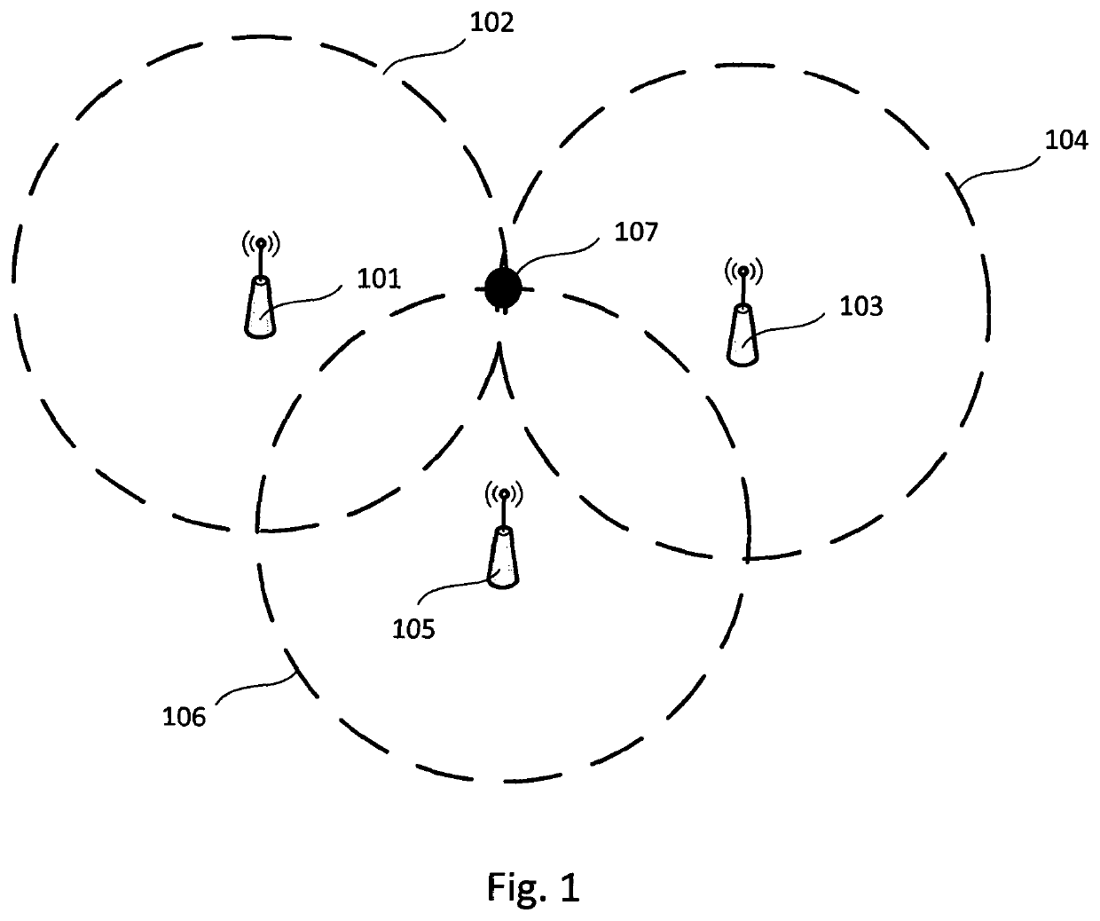
[0143]In a spatial location or geolocation system, independently formed and steered beams emanating from an access point may be steered to enable or minimise communication with a UE and an intersection of two or more regions of an antenna radiation pattern within which poor communications between a UE and an access point result, where two or more regions of an antenna radiation pattern emanate from an access point, which may be the same access point in both cases, may be used wholly or in part to approximately spatially-locate a UE which is in communication with an access point. Regions of an antenna radiation pattern within which poor communications between a UE and an access point may occur and as discussed above are sometimes referred to as ‘nulls’ in a radiation pattern.

third embodiment

[0144]In a spatial location or geolocation system, independently formed and steered beams emanating from an access point may be steered and signal strength measurements may be made and stored of signals emanating from a UE during a steering or beam sweeping process to form a stored measured radiation pattern, with some or all of those stored signal strength measurements forming the stored radiation pattern being compared or correlated with one or more predetermined reference antenna radiation patterns in order to determine a steering angle or bearing at which a measured and a predetermined radiation pattern are most similar. This steering angle may then be reported as a bearing of a UE relative to a datum, such as a boresight direction of an antenna array forming part of a steerable antenna system or a plane of an antenna array forming part of a steerable antenna system.

fourth embodiment

[0145]In a spatial location or geolocation system, independently formed and steered beams emanating from an access point may be steered and signal strength measurements may be made by a UE and stored of signals emanating from an access point and reported back to an access point by a UE during a steering or beam sweeping process to form a stored measured radiation pattern, with some or all of those stored signal strength measurements forming the stored radiation pattern being compared or correlated with one or more predetermined reference antenna radiation patterns in order to determine a steering angle or bearing at which a measured and a predetermined radiation pattern are most similar. This steering angle may then be reported as a bearing of a UE relative to a datum, such as a boresight direction of an antenna array forming part of a steerable antenna system or a plane of an antenna array forming part of a steerable antenna system.

[0146]In still further variants of the first and s...


PUM


Abstract

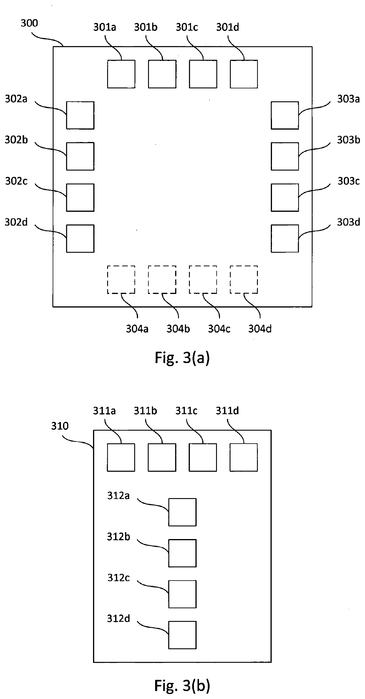
An antenna array is described which is suitable for use in a spatial location system comprising at least one of a transmitter and a receiver together with the antenna array wherein the antenna array is capable of varying the pointing angle of at least two antenna lobes independently without the need to move either the antenna array or its constituent parts physically and wherein the at least two antenna lobes are arranged such that they may partially intersect at one or more pointing angles under electronic control. The antenna array may, for example, comprise at least a first sub-array and at least a second sub-array wherein the second sub-array is oriented substantially orthogonally to the first sub-array and the first and second sub-array share at least one common antenna element.

Description

TECHNICAL FIELD[0001]The present invention relates to Wi-Fi equipment and in particular to an antenna array suitable for use with a Wi-Fi access point which is capable of accurately spatially locating, for example, individual users of that access point or physical items which have been suitably equipped to interact with that access point.BACKGROUND[0002]The reference in this specification to any prior publication (or information derived from it), or to any matter which is known, is not, and should not be taken as an acknowledgment or admission or any form of suggestion that the prior publication (or information derived from it) or known matter forms part of the common general knowledge in the field of endeavour to which this specification relates.[0003]A Wi-Fi access point consists of one or more transmit channels, for sending digital information to an item of user equipment (UE) and one or more receive channels for receiving digital information from a UE. Items of user equipment ca...

Claims


Application Information

Patent Timeline
Patent Type & Authority Applications(United States)
IPC IPC(8): H01Q21/00H01Q21/06H01Q21/24H01Q25/00H01Q9/04
CPCH01Q21/0006H01Q21/065H01Q9/0457H01Q25/001H01Q21/24H01Q1/007H01Q9/0435H01Q21/28H04B7/0413H04B7/0617H04B7/10G01S5/06
Inventor KENINGTON, PETER
Owner ZONEART NETWORKS LTD
Learn More