Compressor device and a cooler thereby used

a compressor device and cooler technology, applied in the direction of machines/engines, liquid fuel engines, light and heating apparatus, etc., can solve the problems of affecting the cooling effect of the compressor device, the temperature of the coolant when leaving the compressor device is relatively low, and the parallel supply is not optimal, etc., to achieve the effect of low compression efficiency, good heat recovery possibility, and less emphasis on compression efficiency

Active Publication Date: 2019-10-29
ATLAS COPCO AIRPOWER NV
View PDF14 Cites 0 Cited by
  • Summary
  • Abstract
  • Description
  • Claims
  • Application Information

AI Technical Summary

Benefits of technology

[0013]The purpose of the present invention is to provide a solution to the aforementioned and other disadvantages by placing less emphasis on the compression efficiency and rather considering the cooling from the perspective of finding an optimum combination of high compression efficiency, good possibility of heat recovery, and minimising the costs of the cooling installation; or from the perspective of an optimum combination of two of the three objectives stated above, depending on the application.

Problems solved by technology

It is also known to cool the compressed gas after the last compressor element before the gas is supplied to the consumer network because otherwise damage could occur to the consumers in the network on account of too high temperatures.
Such a parallel supply of the coolers is highly suitable for optimum compression efficiency but requires a relatively high coolant flow rate for a sufficient supply of coolant to each cooler, which has the disadvantage that such a parallel supply is not optimum with regard to the required pumping power and size of the required cooling circuit and coolers.
Another disadvantage is that the flow rate of the coolant that flows through the coolers must be kept relatively high to bring about maximum cooling, such that the temperature of the coolant when leaving the compressor device is relatively low and as a result is poorly suited for recovering heat therefrom, for example in the form of the provision of hot water or similar.
Moreover, a high flow rate of the coolant also results in high investment costs, high operating costs and high maintenance costs of the cooling installation.
For the purpose of better heat recovery it could be chosen to reduce the flow rate that is driven in parallel through the coolers and thereby increase the temperature of the coolant at the output, but this would be at the expense of the cooling and thus the compression efficiency.

Method used


Image

  • Compressor device and a cooler thereby used
  • Compressor device and a cooler thereby used
  • Compressor device and a cooler thereby used

Examples


Embodiment Construction

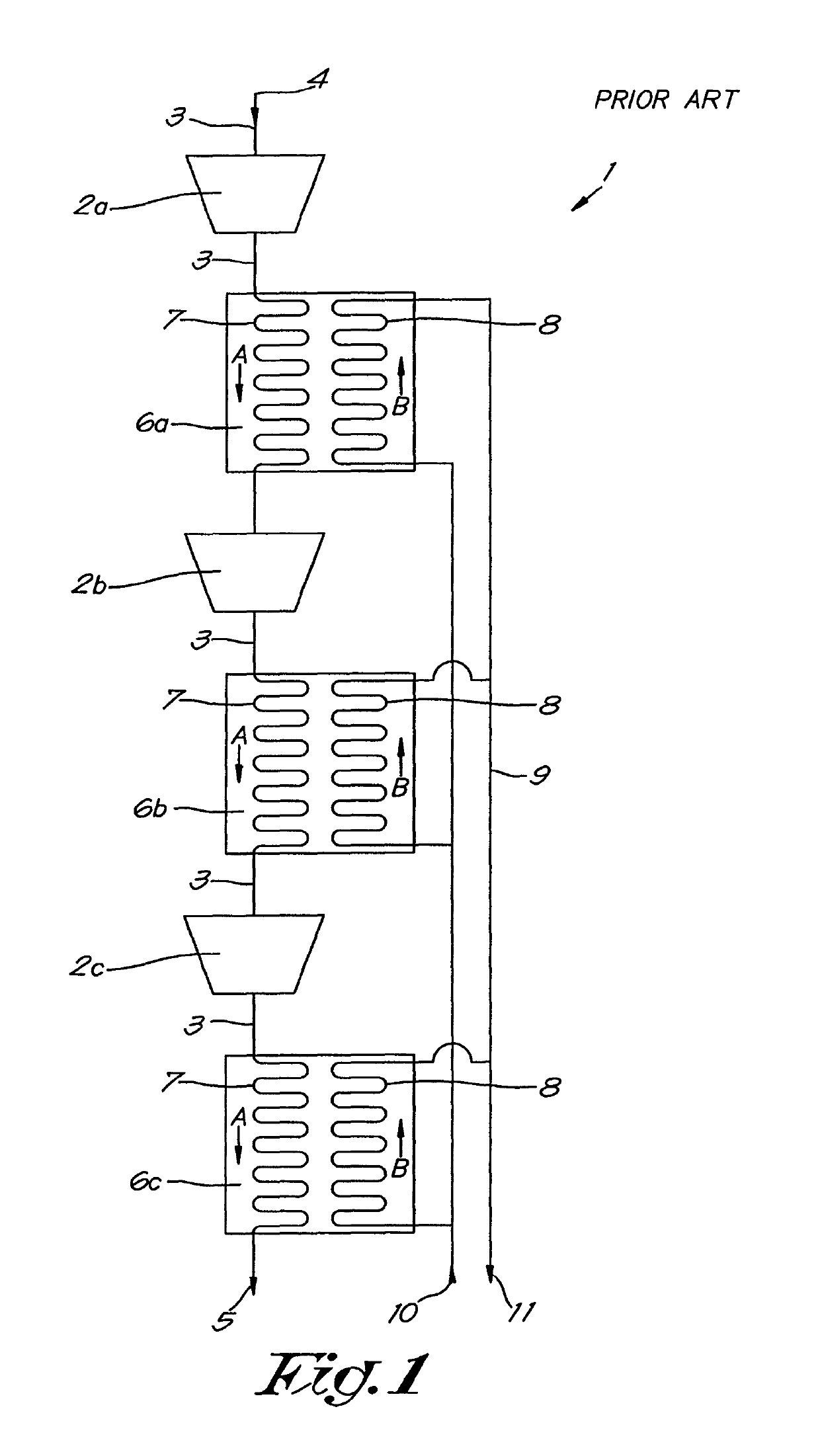
[0043]FIG. 1 shows a conventional compressor device 1 according to the state of the art with three compressor elements 2, respectively 2a, 2b and 2c, which are connected together in series between an inlet 4 and an outlet 5 by means of pipes 3.

[0044]Downstream from each compressor element 2 there is a cooler for cooling the compressed gas, respectively an ‘intercooler’6a between the compressor elements 2a and 2b, an intercooler 6b between the compressor elements 2b and 2c, and an ‘aftercooler’6c after the last compressor element 2c.

[0045]The intercoolers 6a and 6b are thereby intended to cool to a maximum the temperature of the compressed gas from a previous compressor element 2 before being drawn in by a subsequent compressor element 2, and this is to ensure that the efficiency of the compression in the compressor is optimum.

[0046]The aftercooler 6c ensures cooling of the compressed gas before it leaves the compressor device 1 according to the invention via the outlet 5, and this ...


PUM


Abstract

A compressor device with at least two compressor elements connected in series and at least two coolers of which there at least two split coolers that are split in separate successive stages, respectively a hot stage and a cold stage, that are connected together in one or more separate cooling circuits such that the compressed gas is cooled sufficiently between the compressor elements with a minimum coolant flow rate to keep the temperature of the cooled gas at the outlet of each cooler below a maximum permissible value and thereby to realize a desired temperature increase of the coolant in at least one of the aforementioned cooling circuits.

Description

[0001]The present invention relates to a compressor device.[0002]More specifically the invention concerns a compressor device for compressing gas in two or more stages, whereby this compressor device comprises at least two compressor elements connected in series and at least two coolers for cooling the compressed gas, i.e. an intercooler between each of two successive compressor elements and, if need be depending on the configuration, an aftercooler downstream from the last compressor element, whereby each cooler is provided with a primary section through which the compressed gas to be cooled is guided and a secondary section that is in heat-exchanging in contact with the primary section and through which coolant is guided.BACKGROUND OF THE INVENTION[0003]It is known that a gas that is compressed in a compressor element undergoes a substantial temperature increase.[0004]For compressor devices with a number of stages, as referred to here, the compressed gas is supplied from a compres...

Claims


Application Information

Patent Timeline
Patent Type & Authority Patents(United States)
IPC IPC(8): F04C29/04F04D29/58F28F9/02F04C18/16F28D7/16
CPCF04C18/16F28F9/0202F28D7/1607F04D29/5826F04C29/04F04D29/5833F04D29/58
Inventor DE KERPEL, STEFAN PAUL M.
Owner ATLAS COPCO AIRPOWER NV
Why Eureka
Try Eureka