Connector having shell and connector device

a connector and shell technology, applied in the direction of coupling device connection, two-part coupling device, coupling protective earth/shielding arrangement, etc., can solve the problems of easy deformation of elastic arm and connector damage, and achieve the effect of tensile strength

Active Publication Date: 2019-10-29
HIROSE ELECTRIC GROUP
View PDF21 Cites 2 Cited by
  • Summary
  • Abstract
  • Description
  • Claims
  • Application Information

AI Technical Summary

Benefits of technology

[0017]According to the present invention, the tensile strength when an attempt is made to forcibly detach the connector from the partner connector after the connector and the partner connector have been fitted to each other can be enhanced.

Problems solved by technology

However, this configuration of Patent Literature 1 has a problem that when the connector is forcibly detached from the partner connector after the connector and the partner connector have been fitted to each other, an elastic arm easily deforms, and as a result, the connector is damaged.

Method used


Image

  • Connector having shell and connector device
  • Connector having shell and connector device
  • Connector having shell and connector device

Examples


Embodiment Construction

[0031]Hereinafter, a connector and a connector device according to one preferred embodiment of the present invention will be described with reference to the drawings.

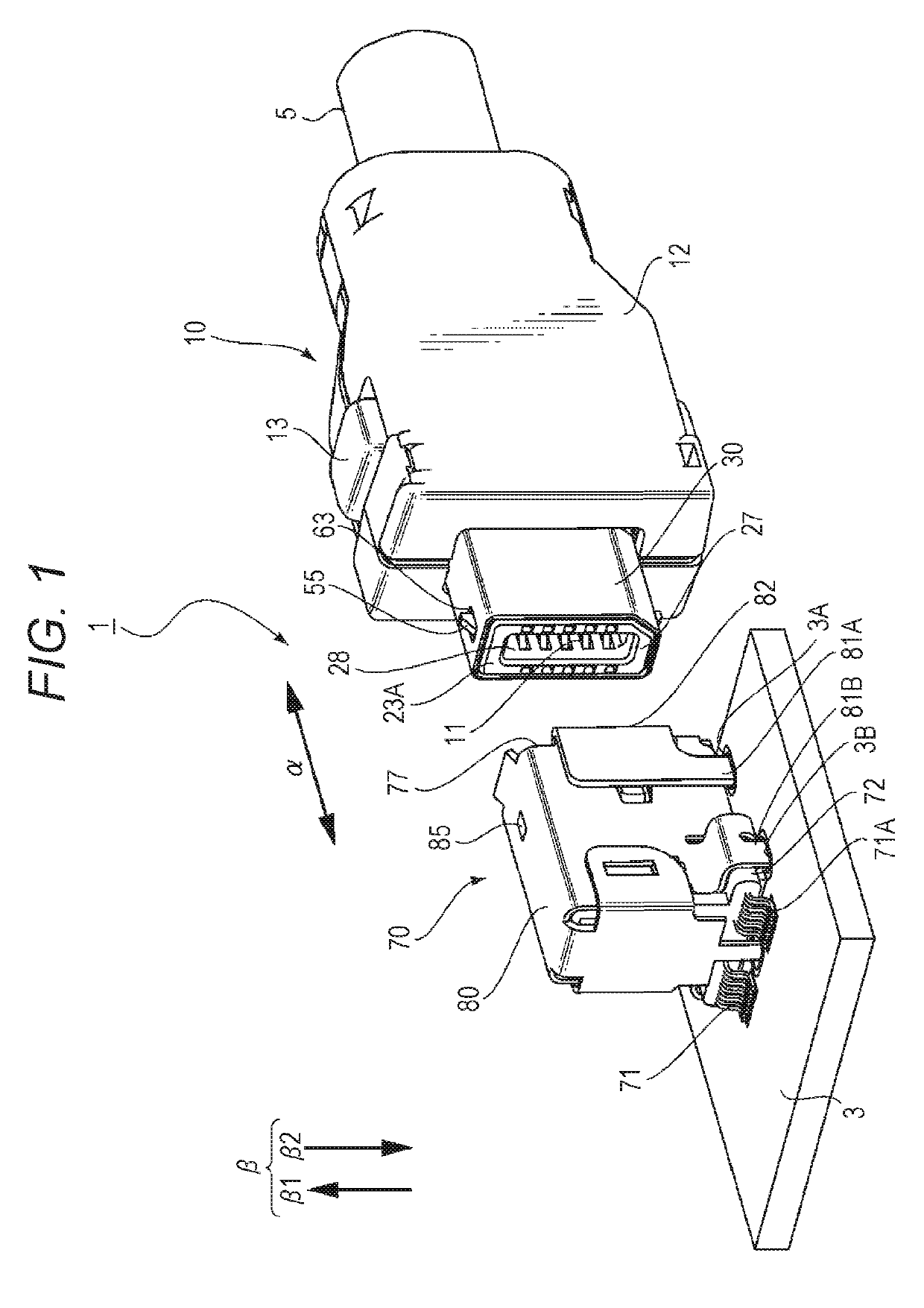
[0032]FIG. 1 illustrates a perspective view of a connector device 1 according to one preferred embodiment of the present invention. The connector device 1 includes a group of a connector 10 and a partner connector 70 fittable to each other. The connector 10 may be, for example, a cable connector connected to an electric cable 5, and on the other hand, the partner connector 70 may be, for example, a substrate connector connected to a substrate 3. An electric cable connector will be described herein as a preferred example, but needless to say, it is not intended to limit the present invention to the electric cable connector. With a connector structure for which a configuration of the present invention can be employed, the present invention is applicable to various connector devices. For example, the present configuration ...


PUM


Abstract

Provided is a connector configured so that tensile strength when an attempt is made to forcibly detach the connector from a partner connector can be enhanced. A housing includes a body portion and a fitting target portion extending to the side of fitting to the partner connector. The diameter of a side portion outer peripheral surface of the fitting target portion is, at at least part thereof, smaller than that of the body portion. A conductive shell includes a first shell and a second shell. The first shell includes a cover portion configured to cover at least part of an outer peripheral surface of the housing, an elastic arm having a free end on the side of fitting to the partner connector, and a support portion elastically connecting the cover portion and the elastic arm and configured to support the elastic arm in a cantilever manner. The elastic arm has a lock portion configured to lock fitting to the partner connector, and has a stepped portion corresponding to a stepped surface of the housing provided using a difference in the diameter. The second shell includes a portion facing the stepped portion at a position closer to the side of fitting to the partner connector than the stepped portion of the elastic arm.

Description

TECHNICAL FIELD[0001]The present invention relates to a connector including a shell and a connector device.BACKGROUND ART[0002]JP-A-2002-367732 (Patent Literature 1) describes one example of a connector having a lock mechanism using a shell. The connector of this type has been utilized as an interface of electronic equipment such as a mobile phone, a PDA, or a personal computer. For these types of electronic equipment, high-speed signal operation has been developed day by day. The shell is provided, so that a characteristic impedance can be adjusted and a shield effect against electromagnetic wave noise from the outside can be obtained. Patent Literature 1 further describes that the lock mechanism is provided at the shell to suppress casual cancellation of fitting.[0003]An exploded perspective view of a connector 100 disclosed in Patent Literature 1 is illustrated in FIG. 13. Note that an outer hood is not shown in this figure. The connector 100 mainly includes an insulator 103 and ...

Claims


Application Information

Patent Timeline
Patent Type & Authority Patents(United States)
IPC IPC(8): H01R13/658H01R13/6582H01R13/639H01R13/627
CPCH01R13/6273H01R13/6582H01R13/639H01R24/60H01R2107/00
Inventor SAKAIZAWA, TADASHINAGANUMA, KENICHI
Owner HIROSE ELECTRIC GROUP
Why Eureka
Try Eureka