Hammer with lightweight handle

a hammer and handle technology, applied in the field of striking tools, can solve the problems that the core itself does not provide any strength or structural support, and achieve the effect of preventing nail slide and high mechanical advantag

Active Publication Date: 2019-11-05
STEIDTMANN DAVID EDWARD
View PDF14 Cites 7 Cited by
  • Summary
  • Abstract
  • Description
  • Claims
  • Application Information

AI Technical Summary

Benefits of technology

[0019]An aspect of the hammer invention is a center of gravity that is proximate to the end face of the head. The center of gravity is separated from the base of the handle by 85%-95% of the total hammer length, measured between the base of the handle and the end face of the head. Because the center of gravity is proximate to the head, the majority of the weight of the hammer is targeted to the striking face which promotes easier use and better striking.
[0020]Another aspect of the present invention is a handle weight (WTHA) that is at most 20% of total hammer weight (WTTOT) but is preferably between 10%-20%. Because the weight of the handle is lighter relative to the entire weight of the hammer, the center of gravity is closer to the head. Conversely, traditional hammers have handle weights that makeup greater than 25% of total hammer weight. Accordingly, the heavier handles contribute to greater shock and prevent the center of gravity of the hammer from being within 85%-95% of the total hammer length from the base of the handle while maintaining a comfortable head weight (WTHD) between fourteen ounces (14 oz.≈396 g) and twenty-five ounces (25 oz.≈708 g). The light weight handle is made from a single layer of composite material that may be reinforced with additional composite material layers in areas that experience high stress when the hammer is swung and impacts a surface. Additionally, these composite layers are formed around an internal core that is preferably made of foam. However, the core itself is does not provide any strength or structural support once the composite is hardened, thus the internal core may be hollow or made from some other non-structural material.
[0021]Another aspect of the present invention is a handle having an inflection point proximate to the base of the handle to provide multiple gripping sections. In effect, the inflection point allows a user to grip the handle in different locations and at different gripping angles that move relative to the longitudinal axis of the hammer. The inflection point is intended to be within 5 diameters of the striking face from the base of the handle. Accordingly, the multiple gripping positions and axes are proximate to the base of the handle. Thus, the user does not necessarily need to grip the handle at a position significantly closer to the head, and thereby sacrifice leverage when accomplishing varying tasks, as seen in the prior art.
[0023]Another aspect of the head of the present invention is a double nail-pull made up of a pair of notches on opposite sidewalls of the head, slightly offset from the side of the handle. The first notch engages the head of the nail and a user may rotate a portion of the nail of out the wall, board or similar surface to first position. Subsequently, the head of the hammer can be repositioned into a second position where the second notch engages the head of the nail and the first notch engages the shank of the nail. Accordingly, the hammer can again be rotated about the nail-pull and the nail can be completely pulled out of the wall, board or similar surface. This is particularly useful for fully removing the long nails typically used in framing at high levels of mechanical advantage.
[0024]Another aspect of the head of the present invention is a malleable striking face imbedded with the grit materials. This striking face is made up of a plug made from a deformable metal into which hard particles are embedded. In operation, when the striking face hits a fastener, like the head of a nail, with sufficient force the striking face will deform around the struck surface and thereby prevent the striking face from sliding off. Additionally, repeated impacts on the deformable material kneads the surface of the striking face, burying some of the hard particles and exposing others which provide a textured striking face that further prevents nail slide.

Problems solved by technology

However, the core itself is does not provide any strength or structural support once the composite is hardened, thus the internal core may be hollow or made from some other non-structural material.

Method used


Image

  • Hammer with lightweight handle
  • Hammer with lightweight handle
  • Hammer with lightweight handle

Examples


Embodiment Construction

[0052]The following description of the preferred embodiment(s) is merely exemplary in nature and is in no way intended to limit the invention, its application, or uses.

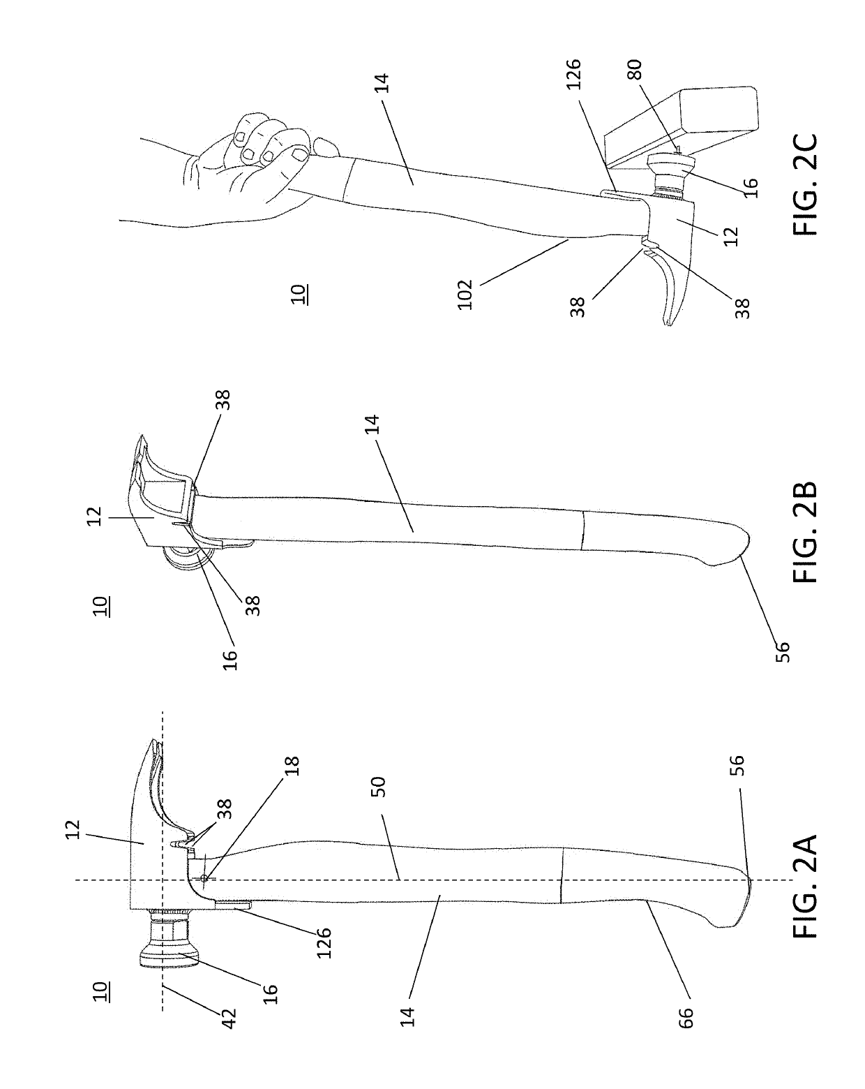
[0053]As illustrated in FIGS. 2A-2C, a hammer 10 has a head 12 that is connected to a handle 14. The handle may be grasped and swung by a user to drive a nail 80, stake or similar fastener and is lightweight, preferably being made from a strong and lightweight composite material like polymer reinforced composite fiber, carbon fiber, fiberglass, Kevlar, and aramid weaves. The hammer head 12 has a striking face 16 used for striking the fastener 80, a claw end 86 opposite the striking face and a head length 44 separating the claw and striking face. The handle is attached to the head at a position opposite the end face 48 and extends away from the head's end face 46a to a handle base 56. The head's longitudinal axis 42 extends between the circular striking face and the end of the hammer's claw and is substantially perpend...


PUM


Abstract

A hammer has a head connected to a lightweight handle with a center of gravity that is proximate to the head of the hammer and separated from the base of the handle by 85%-95% of the total hammer length, measured from the base of the handle to the top side of the head. The handle weight is between 10%-20%. Accordingly, the lighter handle allows the center of gravity of the hammer to be within 85%-95% of the total hammer length from the base of the handle while maintaining a comfortable head weight between 14 oz. and 25 oz. The hammer also has inflection point proximate to the base of the handle providing multiple gripping sections to allow a user to grip the handle in different locations and at different gripping angles that move relative to the longitudinal axis of the hammer.

Description

CROSS-REFERENCE TO RELATED APPLICATIONS[0001]This application claims priority to U.S. Provisional Patent Application Ser. No. 62 / 304,223 filed on Mar. 6, 2016, which is hereby incorporated by reference.STATEMENT REGARDING FEDERALLY SPONSORED RESEARCH[0002]Not Applicable.APPENDIX[0003]Not Applicable.BACKGROUND OF THE INVENTIONField of the Invention[0004]The present invention relates to striking tools, and more particularly to light weight hammer handles that are made of layered composite materials.Related Art[0005]Hammers are well known for driving and prying nails and are used both commercially by framers, roofers and construction workers as well as in non-commercial settings for various uses. Generally, hammers are made up a head attached to the end of a handle which can be grasped by a user and swung to hit and drive a nail, stake, or similar fastener into a desired position. Accordingly, the functionality of hammers has largely remained unchanged where the earliest hammers satisf...

Claims


Application Information

Patent Timeline
Patent Type & Authority Patents(United States)
IPC IPC(8): B25D1/12B25D1/04
CPCB25D1/045B25D1/12B25D1/02B25D1/04B25D1/08B25D2250/111B25D2250/245B25G1/01B25G1/102B25G3/26B25G3/30
Inventor STEIDTMANN, DAVID EDWARD
Owner STEIDTMANN DAVID EDWARD
Why Eureka
Try Eureka