
Vertical sliding valve arm

a valve arm and vertical technology, applied in the direction of valve arrangements, machines/engines, mechanical equipment, etc., can solve the problems of poor power transmission, poor fuel consumption rate, and inability to use a spring to close the valve, so as to reduce the reciprocation weight, improve the fuel consumption rate, and reduce the pressure of the valve spring

Active Publication Date: 2019-11-05
BARBER MICHAEL D
View PDF6 Cites 2 Cited by
  • Summary
  • Abstract
  • Description
  • Claims
  • Application Information

AI Technical Summary

Benefits of technology

This invention aims to solve the problems associated with valve float in high rpm motors by eliminating the conventional pivot rocker arm and reducing or eliminating valve train parts breakage due to valve float.

Problems solved by technology

Using a spring to close a valve is not desirable because of the dynamic motion in engines, typically involving high revolutions per minute (rpm).
This can cause spring wear and valve float that results in poor power transmission and poor fuel consumption rates.
Valve float refers to a scenario where the valve actuation is not aligned with the shape of the camshaft lobe and may result in catastrophic failure if the closing valve makes contact with the piston.
Pivoting rocker arm and valve spring failure is another common malady in high-performance racing engines.
However, desmodromic valves are costly, labor-intensive, and difficult to mass produce.

Method used


Image

  • Vertical sliding valve arm
  • Vertical sliding valve arm
  • Vertical sliding valve arm

Examples


Embodiment Construction

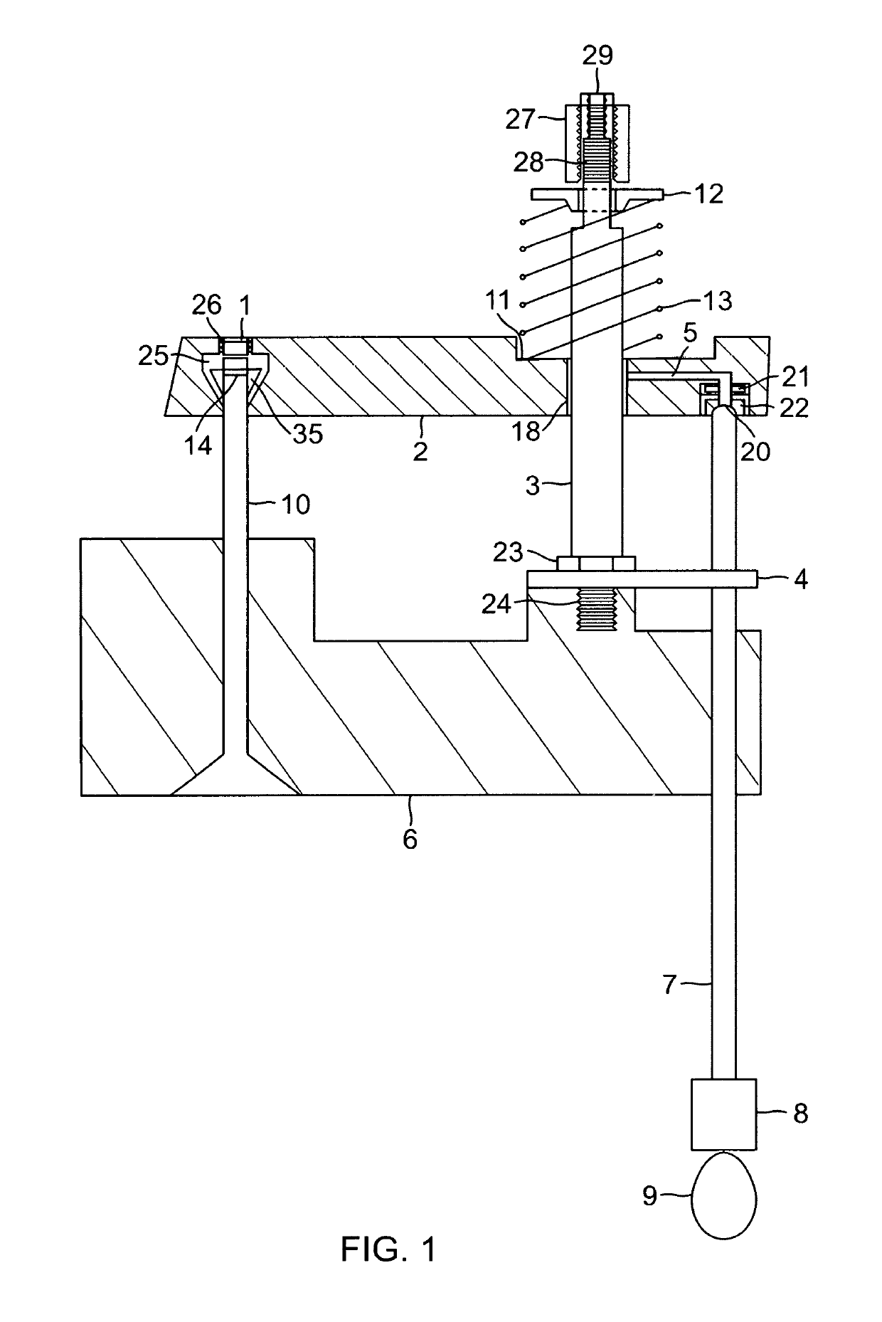
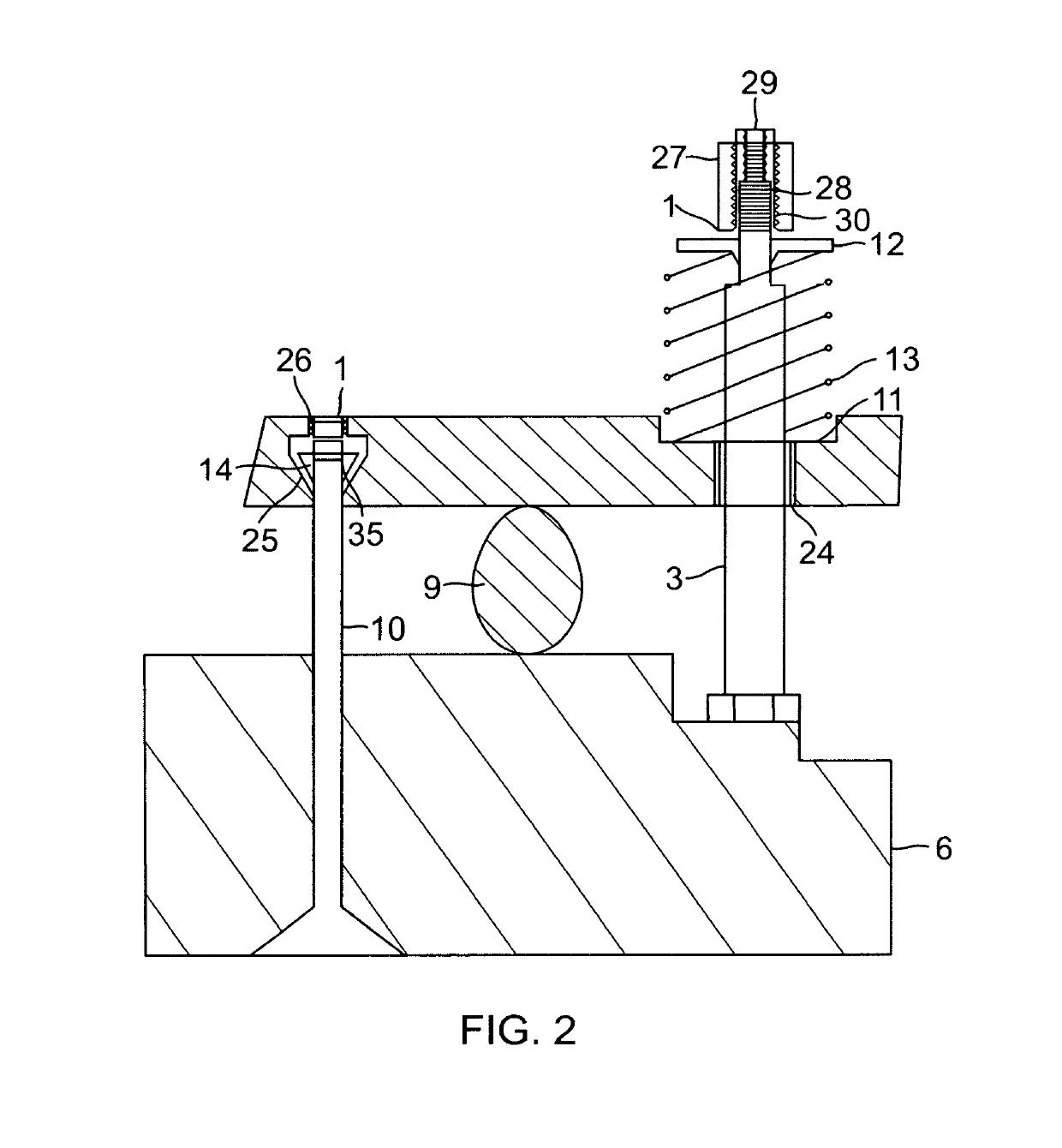
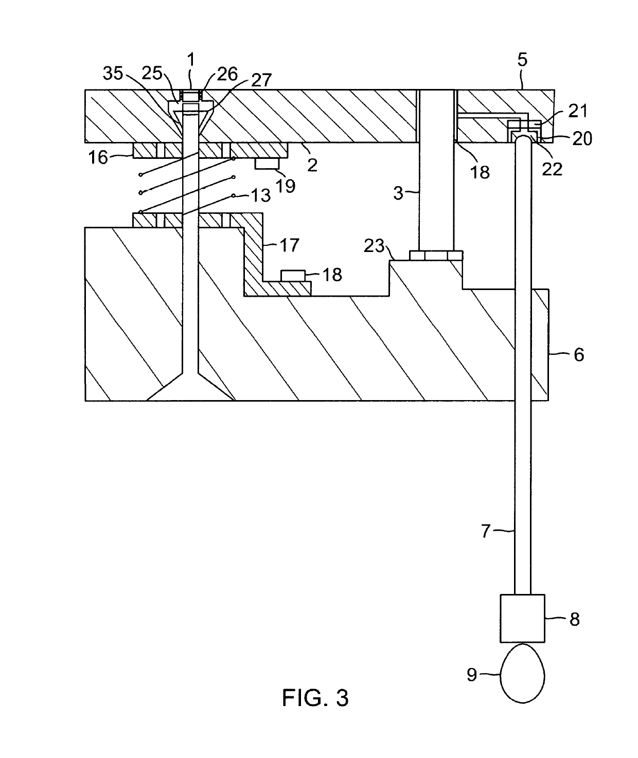
[0034]The present invention uses a vertical sliding valve arm activated by the camshaft to close an engine valve and a valve spring to open the valve. In one non-limiting example, the invention may be configured as illustrated in FIG. 1, which shows the preferred embodiment with the sliding arm mounted on the cylinder head 6 with a conventional-type valve spring 13 located above the sliding arm 2. The spring is held in place by a valve retainer 12. This retainer is held in place by body and housing 2, which is attached to threaded stem 28 of sliding post 3. The operation is described as follows. As camshaft 9 turns, it pushes up on lifter 8 and also pushes up on pushrod 7 that is guided by a pushrod guide plate 4. The end of pushrod 7 fits into the socket of pushrod piston 20, which slides in bore 22. As the pushrod rises, pushrod piston 20 contacts compressible material 21, which can be a compressible material such as rubber. Its purpose is to dampen the closing of the engine valve...


PUM


Abstract

Systems and methods related to eliminating the common pivot-type rocker arm and reversing the use of the valve spring in internal combustion engines. More specifically, the camshaft lobes activate a sliding valve arm to close the engine valve instead of opening it and the valve spring is used to push open the valve instead of closing it.

Description

CROSS REFERENCE TO RELATED APPLICATIONS[0001]This application claims priority to U.S. Provisional Application having Ser. No. 62 / 391,072 filed Apr. 18, 2016, and application having Ser. No. 62 / 391,982 filed May 16, 2016, which is hereby incorporated by reference in its entirety.STATEMENT REGARDING FEDERALLY SPONSORED RESEARCH OR DEVELOPMENT[0002]Not applicable.BACKGROUND[0003]The current way to close an engine valve is to use a spring. This is not desirable because of the dynamic motion in engines, which may cause spring wear and various valve train problems that lead to poor power transmission and poor fuel consumption rates. Valve float is one of the valve train problems and refers to the inability of the valve lifter to properly follow the contour of the camshaft when the engine is operating at high speeds. Since the valve actuation is not aligned with the shape of the camshaft lobe, this may result in catastrophic failure or engine damage if the closing valve makes contact with ...

Claims


Application Information

Patent Timeline
Patent Type & Authority Patents(United States)
IPC IPC(8): F01L1/46F01L1/14F01L1/047
CPCF01L1/465F01L1/146F01L1/047F01L1/462F01L1/182F01L1/30F01L1/46F01L3/10F01L2001/054F01L2301/00F01L2810/03
Inventor BARBER, MICHAEL D.
Owner BARBER MICHAEL D
Learn More