Cooling device for engine

a cooling device and engine technology, applied in the direction of machines/engines, mechanical equipment, engine revolutions, etc., can solve the problems of increasing the cost of the device, poor startability, high fuel consumption, etc., and achieve the effect of improving the fuel consumption rate in the initial phase, efficient operation, and fine cooling control

Active Publication Date: 2013-06-06
MITSUBISHI HEAVY IND ENGINE & TURBOCHARGER LTD
View PDF12 Cites 29 Cited by
  • Summary
  • Abstract
  • Description
  • Claims
  • Application Information

AI Technical Summary

Benefits of technology

[0019]Because of this configuration, the temperature of the cylinder and / or the cylinder head when the engine is running can be monitored in real-time, therefore fine cooling control can be performed during transient operation, and efficient operation becomes possible.
[0020]Furthermore over-cooling of the piston in the initial phase of starting the engine can be prevented, and the fuel consumption rate in the initial phase can be improved.
[0021]When the engine is started (engine cooled state), cooling of the piston is stopped by diverting the oil from the oil pump before reaching the oil injection nozzle, so as to increase the temperature of the piston quickly, whereby startability of the engine is improved, the fuel consumption rate is improved due to a decrease in the warm-up period, and cost can be reduced.

Problems solved by technology

This means that the temperature of the piston head does not rise quickly, and that it takes time until the engine reaches the best operating conditions, in other words startability is not good and fuel consumption is high.
Furthermore according to Patent Document 1, the warm-up oil supply unit that supplies a warm-up oil when cooing the engine and a heating up unit for heating oil are included, which increase the cost of the device, and is also not desirable in terms of fuel consumption.

Method used


Image

  • Cooling device for engine
  • Cooling device for engine
  • Cooling device for engine

Examples


embodiment 1

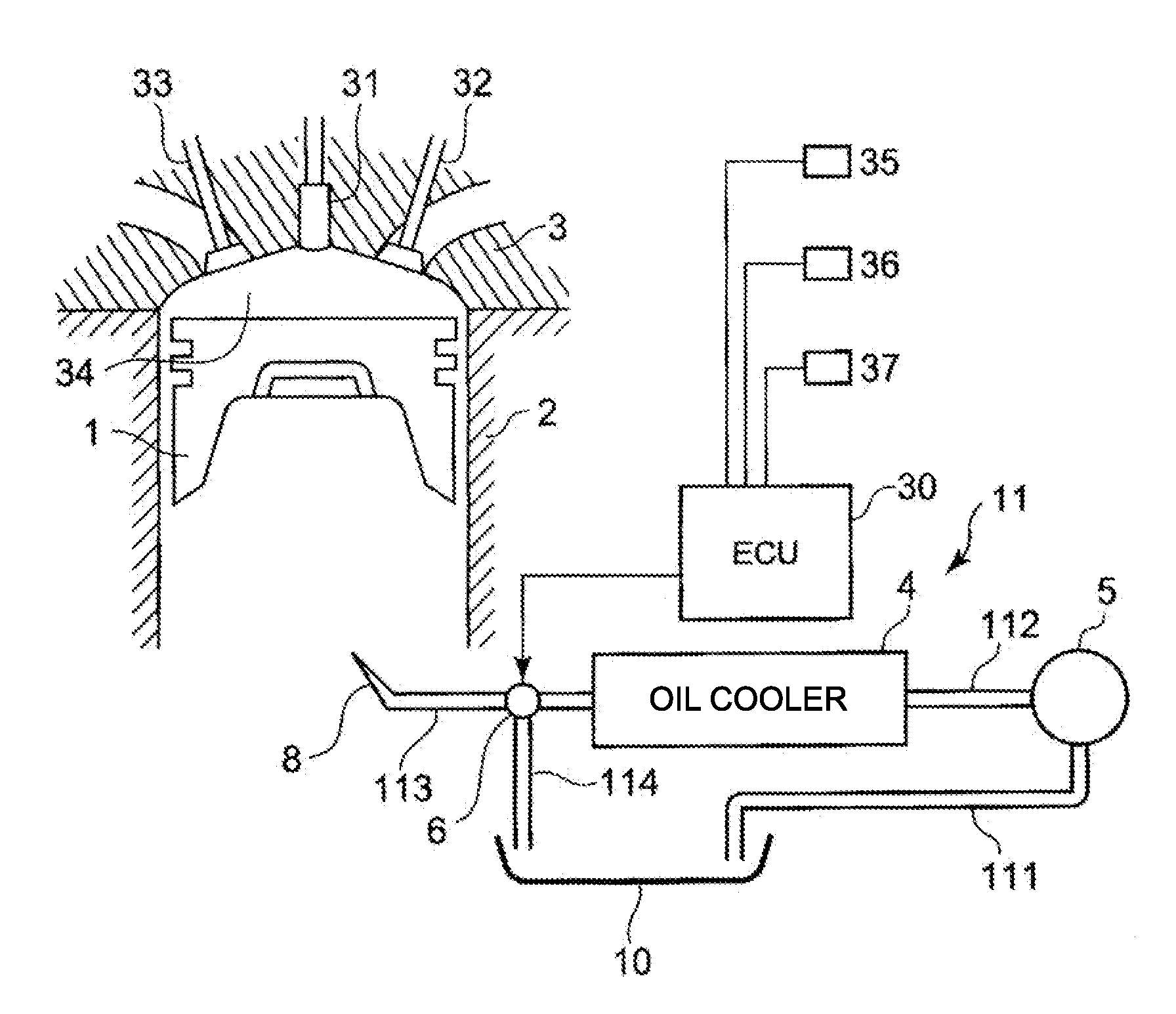
[0033]FIG. 1 shows a piston 1 which vertically slides in a cylinder 2 formed in an engine main unit.

[0034]A cylinder head 3 is installed in an upper part of the piston 1 so as to close the cylinder 2. In the cylinder head 3, a fuel injection nozzle 31 that injects fuel into a combustion chamber 34, an inlet valve 32 that introduces air into the cylinder, and an exhaust valve 33 that exhausts combustion gas are installed.

[0035]An oil injection unit 8 is secured in the engine main unit (not illustrated) facing the rear face of the piston 1 in the lower part of the piston 1.

[0036]5 denotes an oil pump which is connected to a crankshaft (not illustrated) of the engine via a gear train, and is driven simultaneously with the start of the engine, to draw up cooling oil from an oil pan 10 of the engine.

[0037]An oil cooler 4 is normally installed on the side of the engine main unit, and cools the cooling oil using the cooling water of the engine.

[0038]6 denotes a first switching adjustment v...

embodiment 2

[0055]An engine cooling device according to Embodiment 2 will be described with reference to the schematic block diagram shown in FIG. 4.

[0056]A composing element the same as in Embodiment 1 is denoted with a same reference symbol, for which description is omitted.

[0057]In a distribution path 12, the cooling oil is drawn up from the oil pan 10 by the oil pump 5 via the first oil feed tube 111. A second switching adjustment valve 7 is inserted into the intermediate portion of the second oil feed tube 112 connecting an oil pump 5 and the oil cooler 4.

[0058]The third oil feed tube 113, which has the first switching adjustment valve 6 in the intermediation portion, is disposed at the downstream side of the distribution path 12 of the oil cooler 4.

[0059]The oil injection nozzle 8 is disposed further at the downstream side.

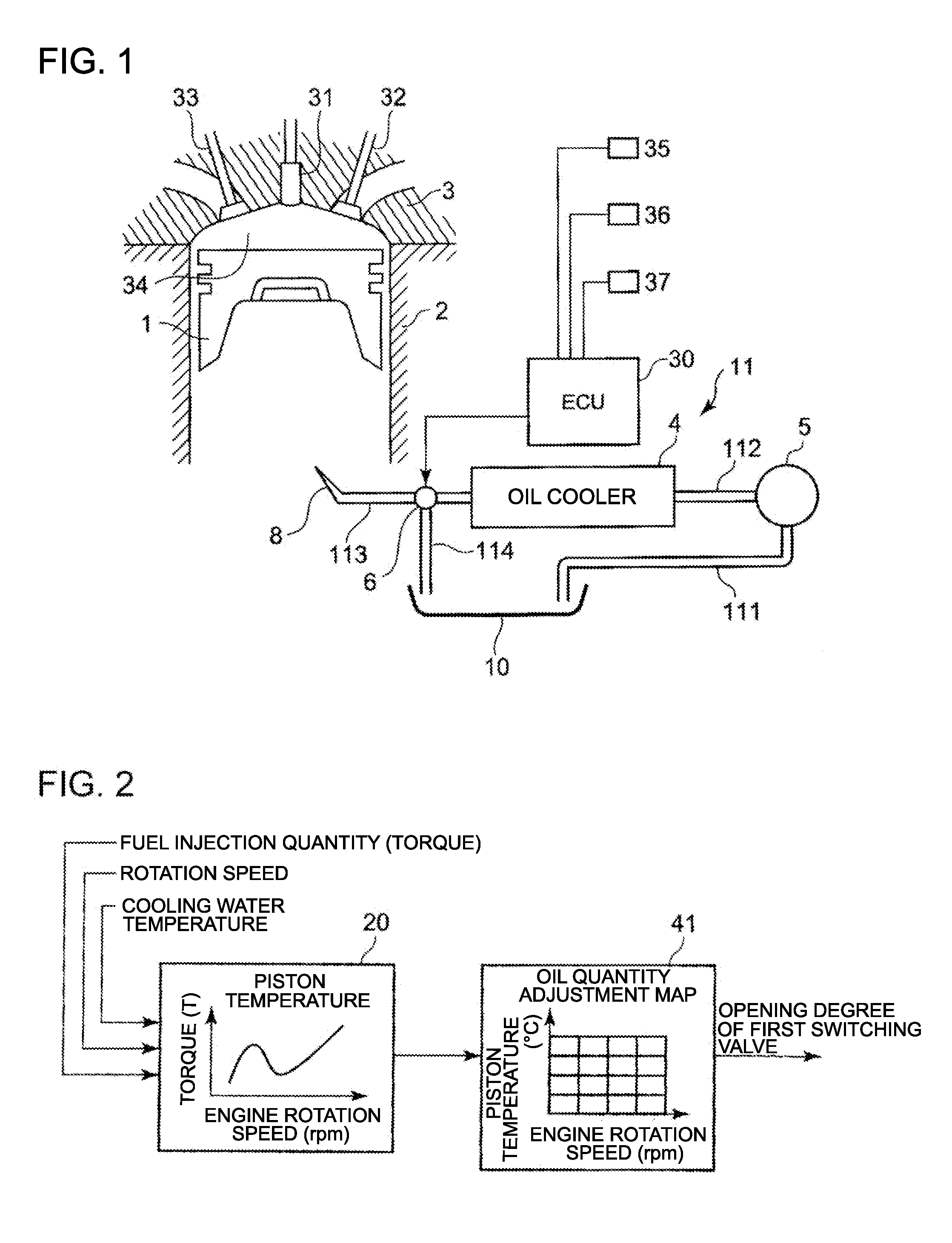
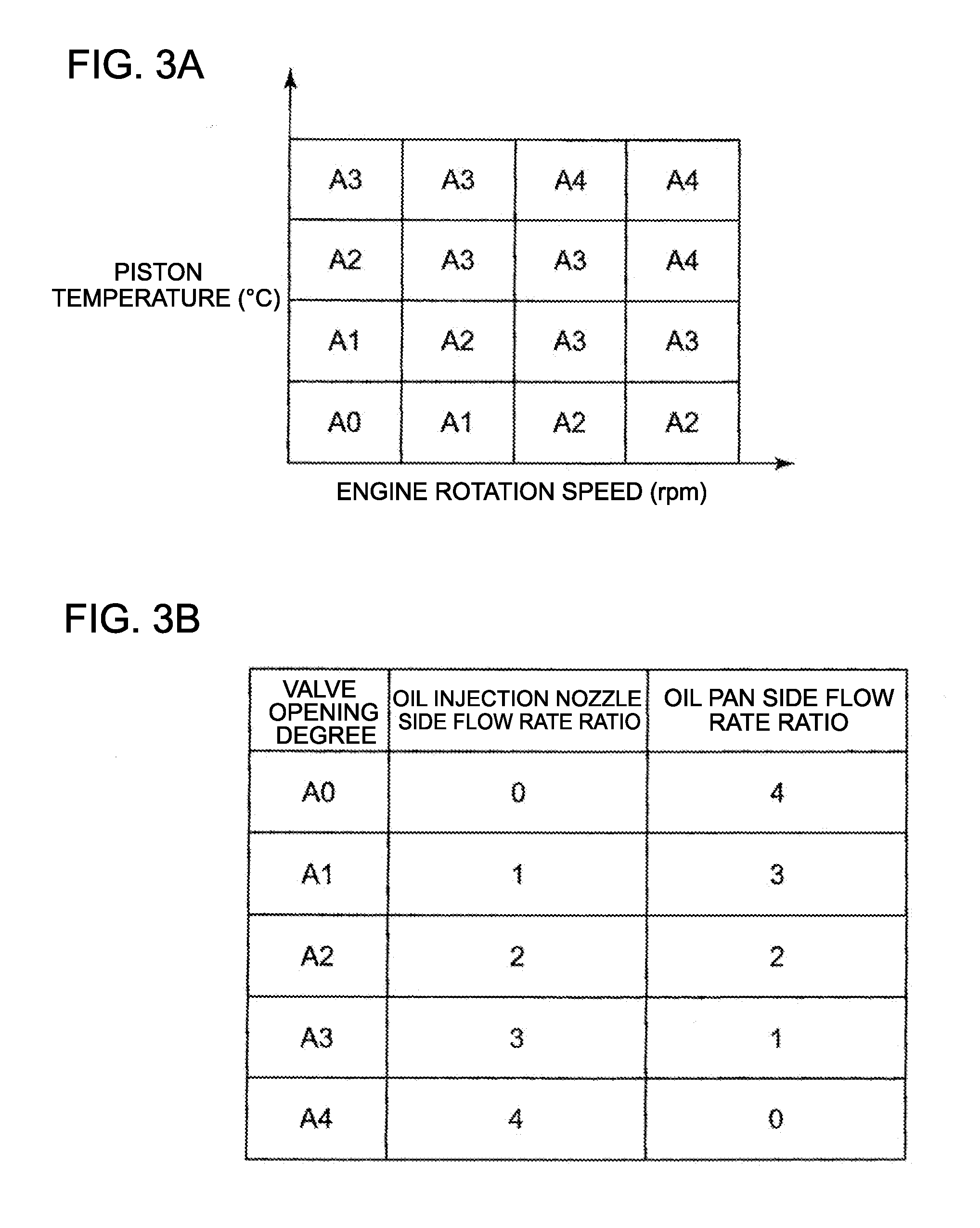
[0060]The first switching adjustment valve 6 is controlled (divides flow) based on an oil quantity adjustment map 41, which is disposed in the control unit 40, and dete...

embodiment 3

[0077]An engine cooling device according to Embodiment 3 will be described with reference to the schematic block diagram shown in FIG. 8.

[0078]A composing element the same as in Embodiment 1 or Embodiment 2 is denoted with a same reference symbol, for which description is omitted.

[0079]In the distribution path 12, the cooling oil is drawn up from the oil pan 10 by the oil pump 5 via the first oil feed tube 111. The second switching adjustment valve 7 is inserted into the second oil feed tube connecting the oil pump 5 and the oil cooler 4.

[0080]The third oil feed tube 113, which has the first switching adjustment valve 6 in the intermediate portion, is disposed in the downstream side of the distribution path 12 of the oil cooler 4, and the oil injection nozzle 8 is disposed further at the downstream side.

[0081]The second switching adjustment valve 7 is connected to the bypass circuit 9, of which one end is connected between the first switching adjustment valve 6 of the third oil feed...


PUM


Abstract

Disclosed is an oil jet device for cooling a piston, including: an oil cooler 4 that is disposed upstream of an oil injection nozzle 8; an oil pump 5 that is disposed upstream of the oil cooler 4; a first switching adjustment valve 6 that is disposed between the oil injection nozzle 8 and the oil cooler 4 and adjusts a flow dividing ratio at which the cooling oil from the oil cooler 4 is distributed to the oil injection nozzle 8 side and to an oil pan side; and a control unit that has an oil quantity adjustment map 4 for switching the first switching adjustment valve 6 based on a piston temperature calculation map 20 for calculating the temperature of the piston 1 using detection values acquired respectively by a cooling water temperature sensor 35, a rotation speed sensor 36 and a load sensor 37.

Description

TECHNICAL FIELD[0001]The present invention relates to a piston cooling device for an engine.BACKGROUND ART[0002]Generally in an engine, a large thermal load is applied to a piston, therefore in order to prevent abnormal combustion, such as engine knock due to high temperature of a piston head, a cooling device, which prevents erosion and abnormal combustion of the piston head by ejecting cooling oil to the rear side of the piston, is used.[0003]As depicted in FIG. 9, which is a schematic of a main section of general piston cooling, an oil pump 5, driven by the driving force of an engine, draws up oil from an oil pan (not illustrated) of the engine while the engine is in operation, and an oil cooler 4 cools the oil by cooling water of the engine.[0004]The oil cooled by the oil cooler 4 is injected from an oil injection nozzle 8 to a rear face of a piston 1, whereby the piston 1 is cooled.[0005]Japanese Patent Application Laid-Open No. 2006-29127 (Patent Document 1) discloses a coolin...

Claims


Application Information

Patent Timeline
Patent Type & Authority Applications(United States)
IPC IPC(8): F01P3/08
CPCF01M1/08F01M1/16F01M2250/62F01M2250/64F01P3/08F01P3/06F01P2060/04F01P2025/30F01P2025/31F01P2025/33F01P2025/62F01P2025/64F01M5/005
Inventor TAKEMOTO, DAISUKE
Owner MITSUBISHI HEAVY IND ENGINE & TURBOCHARGER LTD
Why Eureka
Try Eureka