
Exhaust emission control device

a technology of exhaust emission control and control device, which is applied in electrical control, lighting and heating apparatus, separation processes, etc., can solve the problems of liable misfire, hc and co remaining, and liable to occur furious combustion, and achieve enhanced fuel consumption rate

Inactive Publication Date: 2012-12-20
HINO MOTORS LTD
View PDF3 Cites 3 Cited by
  • Summary
  • Abstract
  • Description
  • Claims
  • Application Information

AI Technical Summary

Benefits of technology

[0013]An exhaust emission control device of the invention can exhibit the following excellent effects.
[0014](1) The fuel consumption rate is enhanced since a plasma fuel reformer as reformed-gas producing means does not appropriate the engine fuel for temperature elevation of the catalyst unlike a catalytic fuel reformer which catalytically reforms the fuel.
[0015](2) Premixed combustion can be conducted just after start-up of the engine in a stable combustion state since plasma discharge generated brings about H2-containing reformed gas.
[0016](3) H2- and CO-containing reformed gas supplied through the nozzle and upstream of the NOx storage reduction catalyst in a direction of flow of the exhaust gas can reduce NOx from the NOx storage reduction catalyst into desorption of N2, CO2 and H2O.

Problems solved by technology

In order to prevent premature ignition in the employment of the premixed combustion to the diesel engine, exhaust gas recirculation (EGR) must be used in combination which returns part of exhaust gas from an engine exhaust passage to an engine intake passage to suppress combustion of the fuel and thus lower temperatures in the cylinders; however, increase in charged amount of the exhaust gas into the cylinders may cause lack of O2 and thus combustion instability so that misfire is liable to occur with unburned HC and CO remaining.
Particularly, in an engine middle or high load region with an injected amount of fuel being increased, the fuel premixed up to the ignition is burned all at once and thus fast and furious combustion is liable to occur; however, since the increase in charged amount (EGR amount) of the exhaust gas to the cylinders may cause misfire as mentioned in the above, studies and researches have been developed, up to the present, on the employment of the premixed combustion only to a low load region.

Method used


Image

  • Exhaust emission control device
  • Exhaust emission control device
  • Exhaust emission control device

Examples


Embodiment Construction

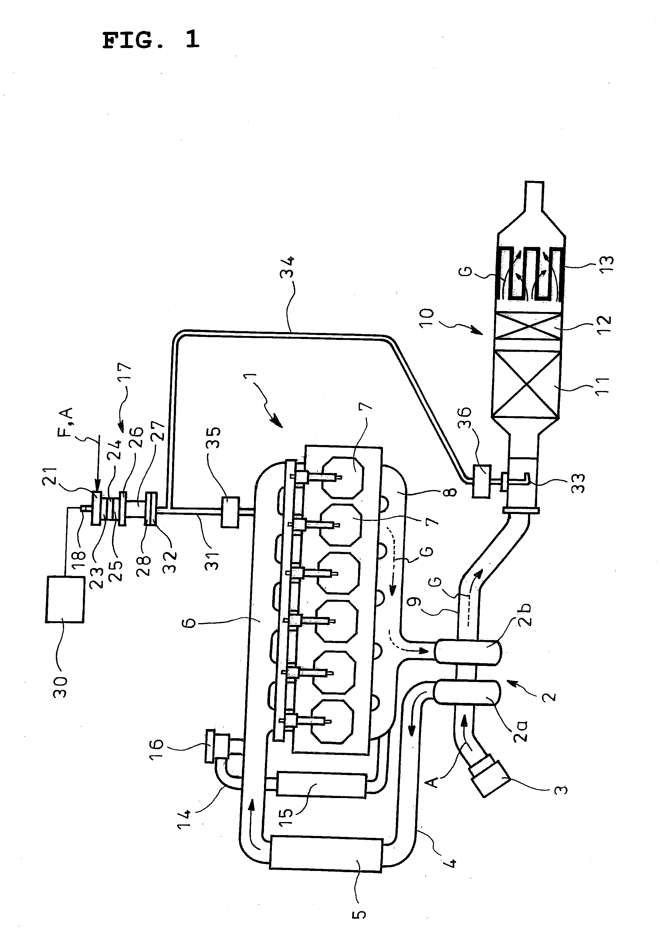
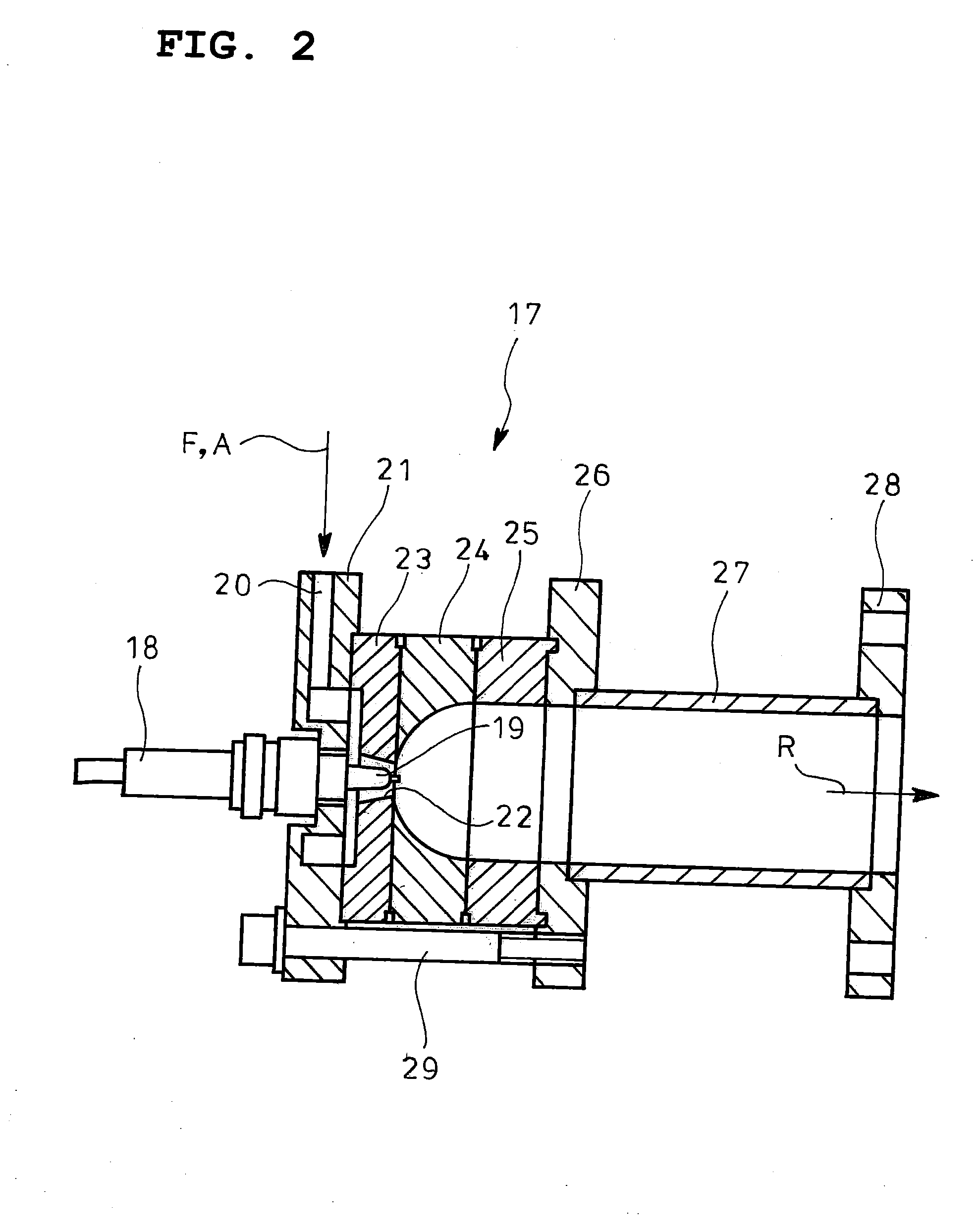
[0019]An embodiment of the invention will be described with reference to the drawings.

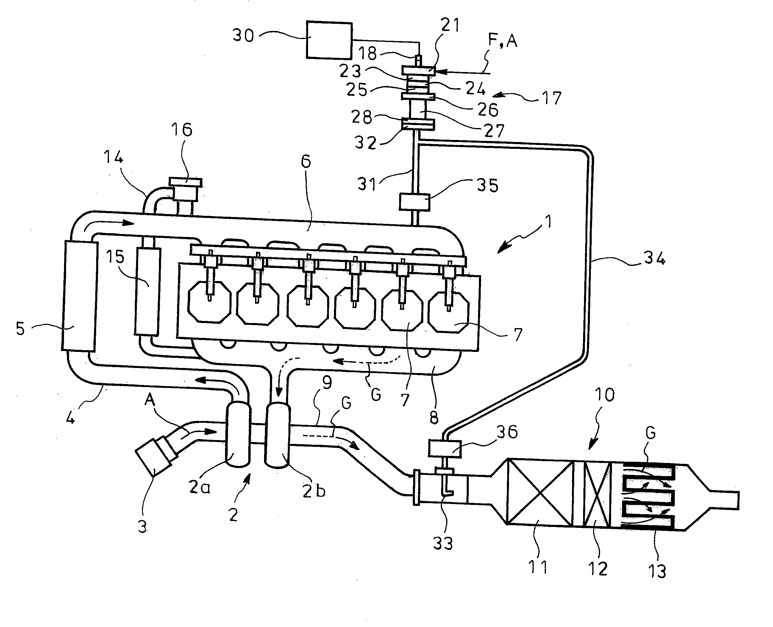
[0020]FIGS. 1 and 2 show the embodiment of the exhaust emission control device according to the invention in which reference numeral 1 denotes an diesel engine with a turbocharger 2. Intake air A introduced through an air cleaner 3 is fed through an intake pipe 4 to a compressor 2a of a turbocharger 2. The intake air A pressurized by the compressor 2a is cooled by an intercooler 5 and is fed to an intake manifold 6 where it is distributed to respective cylinders 7 of the diesel engine 1.

[0021]Exhaust gas G discharged through the respective cylinders 7 of the diesel engine 1 is fed through an exhaust manifold 8 to a turbine 2b of the turbocharger 2. The exhaust gas G having driven the turbine 2b is discharged outside of the vehicle through an exhaust pipe 9 and an aftertreatment device 10.

[0022]The aftertreatment device 10 is constituted by incorporating, in a single casing, a NOx storage reduction ...


PUM

PropertyMeasurementUnit
temperatureaaaaaaaaaa
temperaturesaaaaaaaaaa
combustion instabilityaaaaaaaaaa

Abstract

An exhaust emission control device for a diesel engine 1, in which fuel is injected prior to a compression upper dead center and is ignited and burned after accelerated premixing of the fuel, is provided with a plasma fuel reformer 17 which produces H2-containing reformed gas through plasma discharge using the fuel F as a starting material and supplies the reformed gas through an intake manifold 6 into cylinders 7.

Description

TECHNICAL FIELD[0001]The present invention relates to an exhaust emission control device.BACKGROUND ART[0002]Nowadays under review is employment of premixed combustion to a diesel engine for an automobile which injects fuel not at or near but prior to a compression upper dead center to ignite and burn the fuel after accelerated premixing of the fuel through pre-charge of the same to cylinders, thereby suppressing generation of black smoke.[0003]In order to prevent premature ignition in the employment of the premixed combustion to the diesel engine, exhaust gas recirculation (EGR) must be used in combination which returns part of exhaust gas from an engine exhaust passage to an engine intake passage to suppress combustion of the fuel and thus lower temperatures in the cylinders; however, increase in charged amount of the exhaust gas into the cylinders may cause lack of O2 and thus combustion instability so that misfire is liable to occur with unburned HC and CO remaining.[0004]Partic...

Claims


Application Information

Patent Timeline
Patent Type & Authority Applications(United States)
IPC IPC(8): F02M27/04B01D53/94
CPCF01N3/0842F01N2240/30F01N2250/02F01N2250/12F01N2250/14F01N2430/08F01N2610/04F02B29/0406F02B37/00F02D41/0065F02D41/3035F02D41/0275F01N13/0097F01N13/009F02M26/05
Inventor SHIMODA, MASATOSHI
Owner HINO MOTORS LTD
Learn More