Control device and control method for vehicle

a control device and control method technology, applied in the direction of engine-driven generators, machines/engines, transportation and packaging, etc., can solve the problems of increase of engine torque fluctuations, engine torque rise, etc., to improve fuel economy, and poor controllability of engine torqu

Inactive Publication Date: 2014-04-03
TOYOTA JIDOSHA KK
View PDF7 Cites 11 Cited by
  • Summary
  • Abstract
  • Description
  • Claims
  • Application Information

AI Technical Summary

Benefits of technology

[0009]In starting the engine of the vehicle, as a period of time from timing at which a slip of the engine separating clutch is initiated to timing at which ignition of the engine is initiated (hereinafter, referred to as ignition initiation required time) reduces, an initial rise of an engine torque immediately after initiation of ignition of the engine is steep and engine torque fluctuations increase, so the controllability of the engine torque is poor. Therefore, for example, when the engine torque immediately after initiation of ignition of the engine becomes temporarily smaller than the command value and the slip amount of the lockup clutch is insufficient for the temporary engine torque fluctuations, the lockup clutch being slipped can be inadvertently completely engaged, and, as a result, an engagement shock can occur. In contrast to this, according to the first invention, as the controllability of the engine torque at the time of the engine start deteriorates, the slip amount of the lockup clutch is increased, so it is possible to avoid occurrence of the engagement shock by the adequate slip amount. In addition, as the ignition initiation required time extends, the controllability of the engine torque improves and an engagement shock of the lockup clutch becomes hard to occur, so it is possible to improve fuel economy by reducing the slip amount of the lockup clutch accordingly. In this way, it is possible to achieve both fuel economy and drivability at the time of shifting from the motor drive mode to the engine drive mode. For example, fuel economy is a travel distance per unit fuel consumption, or the like, and improvement in fuel economy means that the travel distance per unit fuel consumption extends or a fuel consumption rate (=fuel consumption / drive wheel output) of the entire vehicle reduces. Conversely, a decrease (deterioration) in fuel economy means that the travel distance per unit fuel consumption reduces or the fuel consumption rate of the entire vehicle increases.
[0010]In the control device, the controller may be configured to reduce the slip amount of the lockup clutch as a rotation speed of output of the fluid transmission device increases. Here, when the engine rotation speed that is increased at the time of the engine start is low, the startability of the engine deteriorates. In this respect, according to the second invention, even when the output rotation speed of the fluid transmission device is low, the engine rotation speed is increased to a certain high speed due to a slip of the lockup clutch at the time of the engine start, so it is possible to suppress deterioration of engine startability due to the low output rotation speed of the fluid transmission device.
[0011]In the control device, the engine may be a direct-injection engine, the controller may be configured to start the engine with the use of any one of a first engine start method, a second engine start method and a third engine start method, the controller may be configured to, in the first engine start method, initiate ignition of the engine simultaneously with initiation of a slip of the engine separating clutch or before the initiation of the slip, the controller may be configured to, in the second engine start method, initiate ignition of the engine within a period from initiation of a slip of the engine separating clutch to when the engine separating clutch is completely engaged, the controller may be configured to, in the third engine start method, initiate ignition of the engine after the engine separating clutch has been completely engaged from a state where the engine separating clutch is slipped, the controller may be configured to reduce the slip amount of the lockup clutch when the engine is started with the use of the third engine start method as compared to when the engine is started with the use of the second engine start method, and the controller may be configured to reduce the slip amount of the lockup clutch when the engine is started with the use of the second engine start method as compared to when the engine is started with the use of the first engine start method. With this configuration, the slip amount of the lockup clutch is set to an appropriate amount on the basis of a specific engine start method, so, even when any one of the engine start methods is employed, it is possible to achieve both fuel economy and drivability at the time of shifting from the motor drive mode to the engine drive mode.
[0012]A second aspect of the invention relates to a control method for a vehicle including an engine, an electric motor, an engine separating clutch and a fluid transmission device. The control method includes, at the time of shifting from a motor drive mode to an engine drive mode by starting the engine in the motor drive mode, starting the engine by slipping the engine separating clutch and igniting the engine in a state where a lockup clutch included in the fluid transmission device is slipped. The fluid transmission device is interposed between the electric motor and a drive wheel. The engine separating clutch is configured to selectively couple the engine to the electric motor. Only the electric motor is a drive source in the motor drive mode. The engine is a drive source in the engine drive mode. The control method includes, at the time of the shifting, reducing a slip amount of the lockup clutch as a period of time from timing at which a slip of the engine separating clutch is initiated to timing at which ignition of the engine is initiated extends.

Problems solved by technology

In starting the engine of the vehicle, as a period of time from timing at which a slip of the engine separating clutch is initiated to timing at which ignition of the engine is initiated (hereinafter, referred to as ignition initiation required time) reduces, an initial rise of an engine torque immediately after initiation of ignition of the engine is steep and engine torque fluctuations increase, so the controllability of the engine torque is poor.
Therefore, for example, when the engine torque immediately after initiation of ignition of the engine becomes temporarily smaller than the command value and the slip amount of the lockup clutch is insufficient for the temporary engine torque fluctuations, the lockup clutch being slipped can be inadvertently completely engaged, and, as a result, an engagement shock can occur.
Conversely, a decrease (deterioration) in fuel economy means that the travel distance per unit fuel consumption reduces or the fuel consumption rate of the entire vehicle increases.

Method used


Image

  • Control device and control method for vehicle
  • Control device and control method for vehicle
  • Control device and control method for vehicle

Examples


Embodiment Construction

[0022]Hereinafter, an embodiment of the invention will be described in detail with reference to the accompanying drawings.

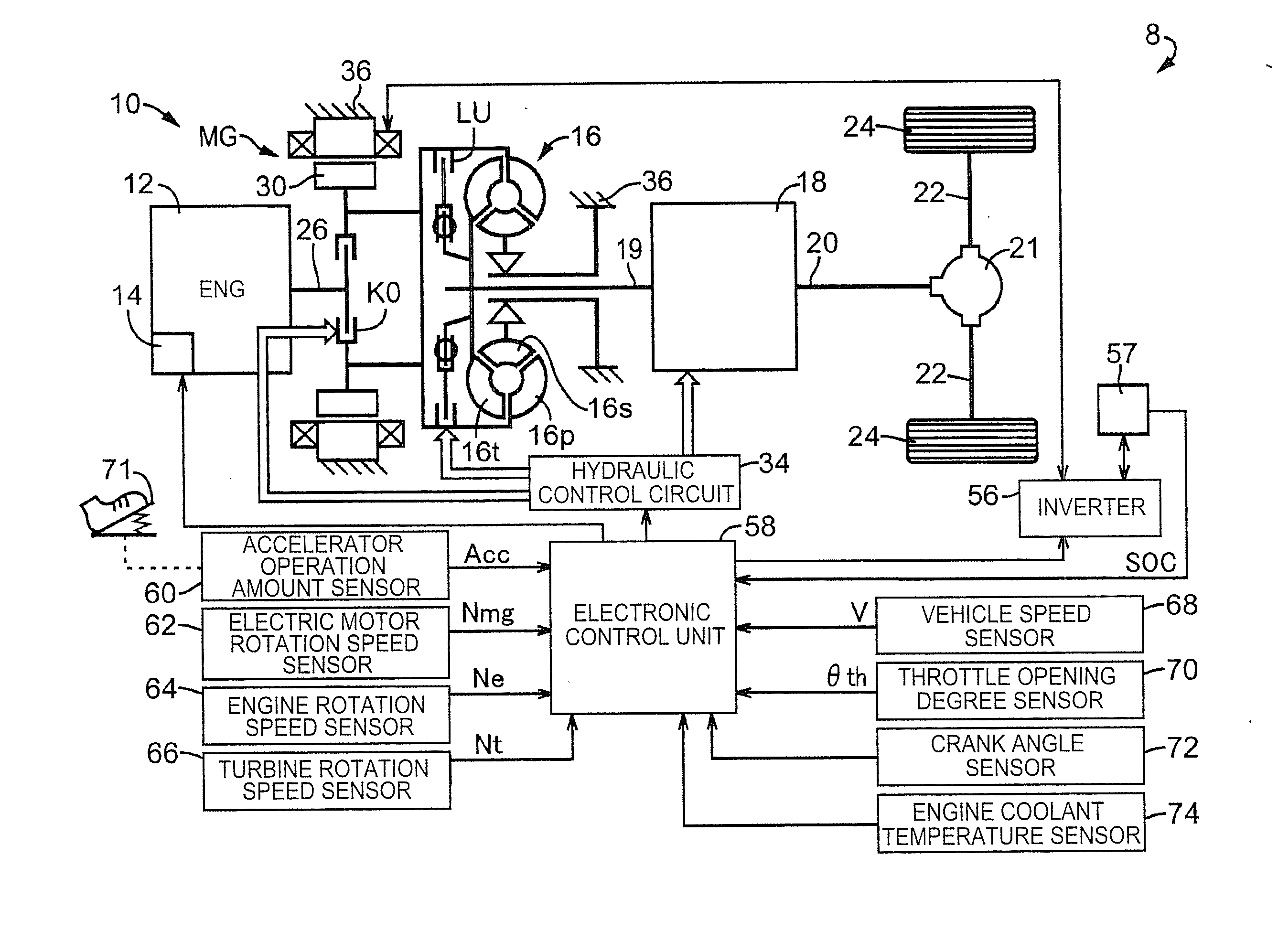
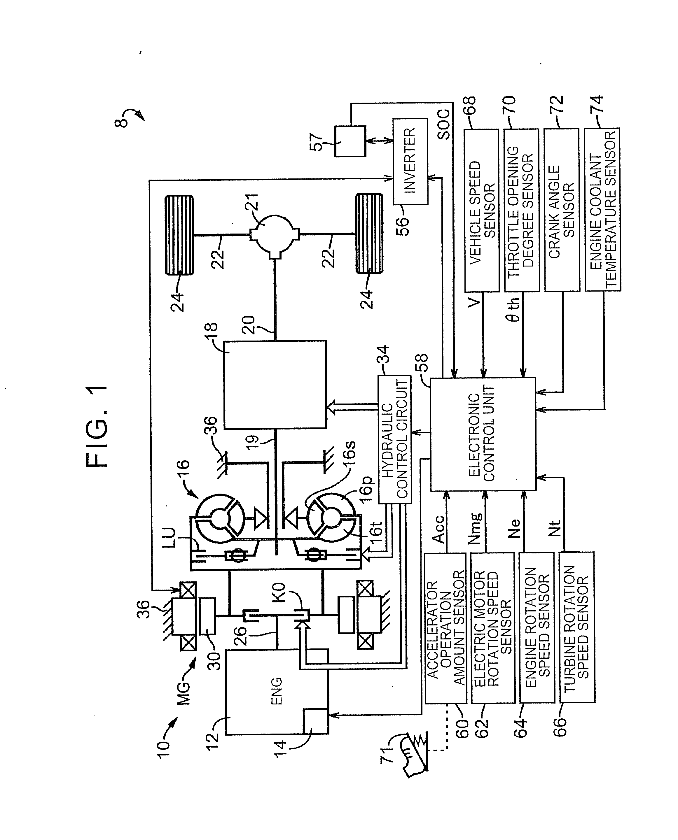
[0023]FIG. 1 is a view that conceptually shows the configuration of a drive system of a hybrid vehicle 8 (hereinafter, simply referred to as “vehicle 8”) according to the embodiment of the invention. The hybrid vehicle 8 shown in FIG. 1 includes a vehicle drive device 10 (hereinafter, referred to as “drive device 10”), a differential gear unit 21, a pair of right and left axles 22, a pair of right and left drive wheels 24, a hydraulic control circuit 34, an inverter 56 and an electronic control unit 58. The drive device 10 includes an engine 12, an engine output control unit 14, an electric motor MG, an engine separating clutch K0, a torque converter 16 and an automatic transmission 18. The engine 12 can function as a traveling drive source. The engine output control unit 14 starts or stops the engine 12 and executes engine output control, such as throttle contro...


PUM


Abstract

A controller of a vehicle control device, at the time of shifting from a motor drive mode to an engine drive mode by starting an engine in the motor drive mode, starts the engine by slipping an engine separating clutch and igniting the engine in a state where a lockup clutch of a fluid transmission device is slipped. The fluid transmission device is interposed between an electric motor and a drive wheel. The engine separating clutch selectively couples the engine to the electric motor. Only the electric motor is a drive source in the motor drive mode. The engine is a drive source in the engine drive mode. The controller, at the time of the shifting, reduces a slip amount of the lockup clutch as a period of time from slip initiation timing of the engine separating clutch to ignition initiation timing of the engine extends.

Description

INCORPORATION BY REFERENCE[0001]The disclosure of Japanese Patent Application No. 2012-220768 filed on Oct. 2, 2012 including the specification, drawings and abstract is incorporated herein by reference in its entirety.BACKGROUND OF THE INVENTION[0002]1. Field of the Invention[0003]The invention relates to improvement in control for starting an engine in a hybrid vehicle.[0004]2. Description of Related Art[0005]There is known a vehicle that includes an engine, an electric motor, an input clutch that selectively couples the engine to the electric motor, and a torque converter having a lockup clutch and interposed between the electric motor and drive wheels. A control device for such a vehicle is, for example, described in Japanese Patent Application Publication No. 2001-032922 (JP 2001-032922 A). When the control device for a vehicle, described in JP 2001-032922 A, shifts from a motor drive mode in which only the electric motor is used as a drive source to an engine drive mode in whi...

Claims


Application Information

Patent Timeline
Patent Type & Authority Applications(United States)
IPC IPC(8): B60W20/00B60L50/16
CPCY10S903/902B60W20/10B60W10/02B60W10/06F02D29/02F16H61/14B60K6/48B60W10/026B60W30/192B60W2710/024B60W20/40Y02T10/62
Inventor YOSHIKAWA, MASATONAKANISHI, NAOKIMATSUTANI, SHINTARO
Owner TOYOTA JIDOSHA KK
Why Eureka
Try Eureka