Fuel gas supply device for gas engine

a gas supply device and gas engine technology, applied in the direction of liquid fuel feeders, machines/engines, mechanical equipment, etc., can solve the problems of increased pumping work amount required for suction of new air or fuel-containing new air into the cylinder, increased fuel consumption rate, and insufficient stirration of sucked air in the inlet path b>2/b>, so as to improve the combustion efficiency in the combustion chamber, inhibit damage, and increase the effect of partial wear

Inactive Publication Date: 2013-12-19
MITSUBISHI HEAVY IND LTD
View PDF9 Cites 4 Cited by
  • Summary
  • Abstract
  • Description
  • Claims
  • Application Information

AI Technical Summary

Benefits of technology

[0022]With such a configuration, during the operation of the inlet valve in the vertical direction, the sliding contact position between the outer circumferential surface of the projection of the inlet valve rod and the outer edge of the fuel gas injection hole changes in the circumferential direction during the operation of the inlet valve. Accordingly, it is possible to inhibit the damages and an increase in partial wear to the outer circumferential surface.
[0023]In the inner circumferential surface of the sleeve into which the projection provided at the inlet valve rod is fitted, fuel gas injection holes situated within the movement region of the projection of the inlet valve rod, and to be opened and closed with the movement of the inlet valve rod are each formed in an ellipse. As a result, the injection period of the fuel gas injected into the inlet path is lengthened, which promotes mixing with the supply air flowing through the inlet path. Accordingly, the combustion efficiency in the combustion chamber is improved, which allows the improvement of the fuel consumption rate.

Problems solved by technology

Accordingly, the gas injection nozzle becomes a resistance against the flow of the sucked air, resulting in an increase in pumping work amount required for suction of new air or fuel-containing new air into a cylinder.
This causes an increase in fuel consumption rate.
However, in accordance with the structure of Patent Document 2, when the fuel gas injected into the inlet path 2 is injected in a short time, the fuel gas in the inlet path 2 and the sucked air may not be stirred sufficiently.

Method used


Image

  • Fuel gas supply device for gas engine
  • Fuel gas supply device for gas engine
  • Fuel gas supply device for gas engine

Examples


Embodiment Construction

[0029]Below, the present invention will be described in details by way of embodiments shown in the accompanying drawings.

[0030]However, the dimensions, materials, shapes, the relative arrangement thereof, and the like described in the embodiments are, unless otherwise specified, not construed as limiting the scope of the invention only thereto, and are only mere illustrative examples.

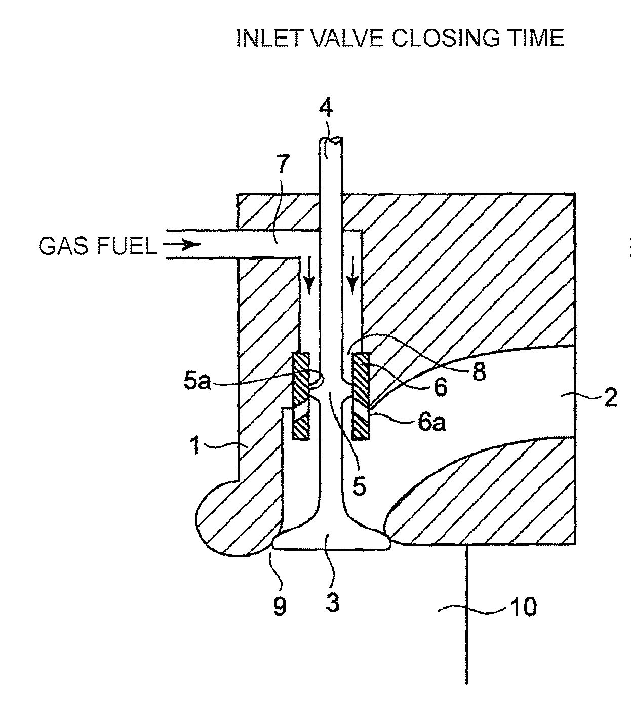
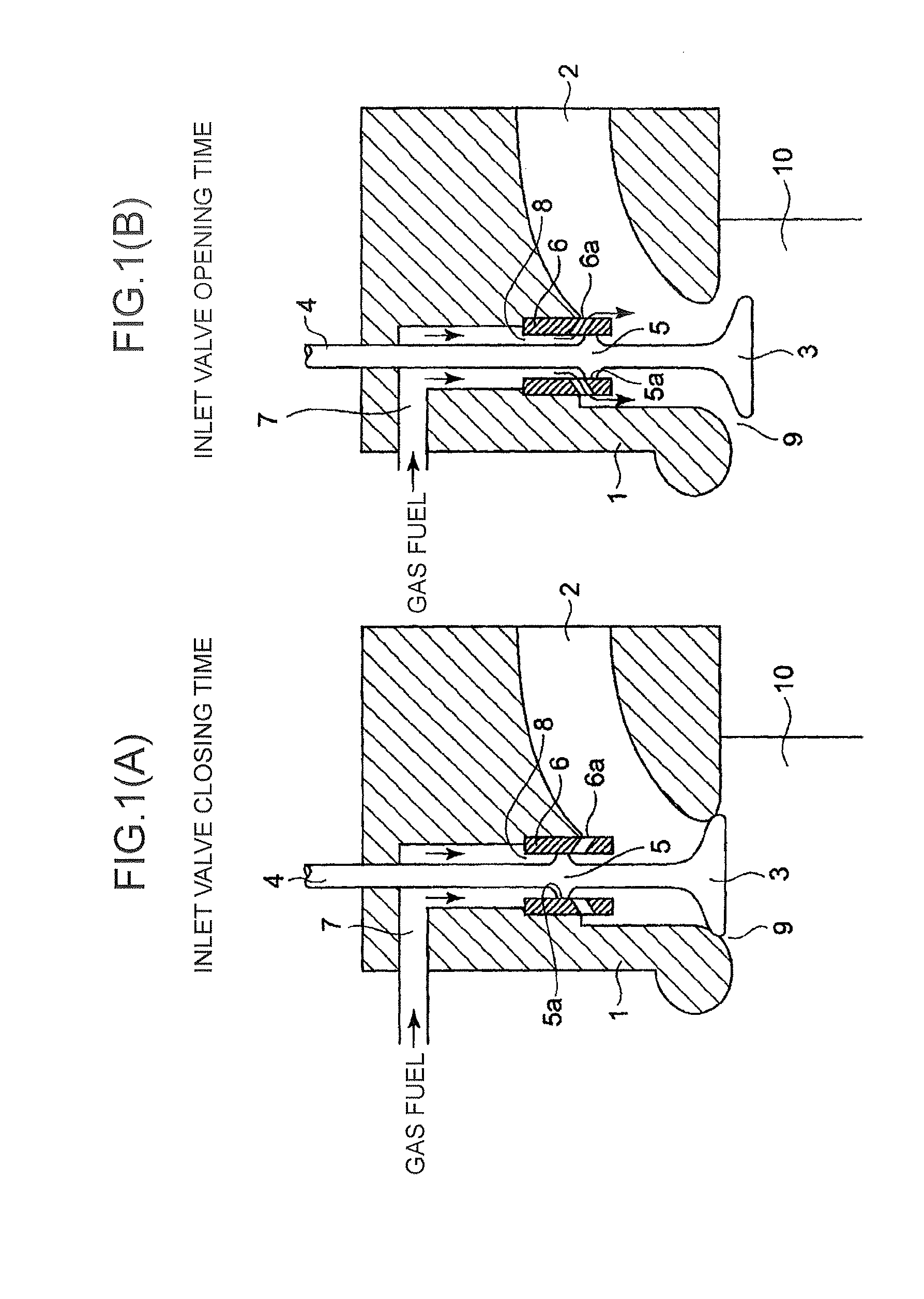
[0031]In FIG. 1, 1 is a cylinder head; 2, an inlet path in the cylinder head 1; 3, an inlet valve; and 4, an inlet valve rod of the inlet valve 3. The inlet valve rod 4 is provided with a projection 5 having a larger diameter than the inlet valve rod 4 and having a cylindrical surface 5a concentric with the inlet valve rod 4 and in parallel with the inlet valve rod 4. The circumferential surface 5a of the projection 5 is slidably fitted into a sleeve 6 (ordinary name: gas valve seat) fixed to the cylinder head 1 so as to protrude into the inlet path 2 in the cylinder head 1.

[0032]In an example in FIG. 1...


PUM


Abstract

There is provided a fuel gas supply device for a gas engine in which a fuel gas flows along the axial direction on the outer circumferential side of an inlet valve rod, and is supplied to an inlet path in a cylinder head. The device is characterized in that fuel gas injection holes to be opened and closed with the movement of a projection are provided in the inner circumferential surface of a sleeve into which the projection is slidably fitted, the projection being provided at the inlet valve rod, having a larger outer diameter than the inlet valve rod and having a portion concentric with and in parallel with the inlet valve rod, and in that the fuel gas injection holes are each formed in an ellipse, and the opening upper and lower end region part of the ellipse is situated within the movement region of the projection.

Description

TECHNICAL FIELD[0001]The present invention relates to a fuel gas supply device for supplying a fuel gas of a gas engine into an inlet path.BACKGROUND ART[0002]As one example of a configuration of a gas engine for mixing an air flowing through an inlet path and a fuel gas, there is a configuration in which an injection nozzle is connected to a gas supply pipe, so that the fuel gas is injected through the nozzle into an inlet manifold.[0003]In that case, the injection nozzle for the fuel gas protrudes into the inlet manifold. For this reason, the airflow in the inlet manifold is disturbed, so that the circulation resistance against the sucked air tends to increase.[0004]In a conventional gas engine in which a fuel gas is supplied to the inlet path, as disclosed in, for example, Japanese Patent Application Laid-open No. H9-268923 (Patent Document 1), a gas injection nozzle is disposed across an inlet pipe. Accordingly, the gas injection nozzle becomes a resistance against the flow of t...

Claims


Application Information

Patent Timeline
Patent Type & Authority Applications(United States)
IPC IPC(8): F02M69/00
CPCF01L3/08F01L3/20F01L2820/01Y02T10/32F01L2820/02F02M69/00F02M21/026F01L3/24F02M21/042Y02T10/30
Inventor ISHIDA, MICHIYASUESAKI, MINORU
Owner MITSUBISHI HEAVY IND LTD
Why Eureka
Try Eureka