System and method for detecting contaminants on a circuit

a microelectronic circuit and microelectronic technology, applied in the direction of fluorescence/phosphorescence, semiconductor/solid-state device testing/measurement, instruments, etc., can solve the problems of inability to detect organic epoxy residues on gold wires or gold ribbons bonded to the surface of microelectronic circuit boards using a white light microscopic device, and the detection of organic epoxy residues on gold wires or gold ribbons is difficult, and achieves low cos

Active Publication Date: 2019-11-05
BAE SYST INFORMATION & ELECTRONICS SYST INTERGRATION INC
View PDF8 Cites 1 Cited by
  • Summary
  • Abstract
  • Description
  • Claims
  • Application Information

AI Technical Summary

Benefits of technology

[0005]Therefore, there is need for a new apparatus or system to detect organic resin contaminants on a microelectronic circuit board, which is nonhazardous to an operator and can be built in low cost.
[0012]In one particular example, using a 460 nanometers (nm) blue light source and a 515 nm long pass filter, it is possible to readily visualize cured epoxy resin contaminants and many other contaminants on gold bonded pads / wires / ribbons and other microelectronic components. In one example, a 460 nm blue light demonstrates the possibility to replace a UV fluorescing with blue light fluorescing to detect thin layers of cured epoxy resins on any microelectronic modules.
[0014]In yet another aspect, an example of the present disclosure may provide a system and method utilizing a light source coupled with a viewing device to detect contaminants on an electronic circuit board. This fluorescence microscopy apparatus can be easily integrated into a bench top stereoscope and does not require the use of expensive and destructive analytical techniques. Typically, blue light is used in conjunction with a filter to detect contamination from cured epoxy resins and many other contaminants on gold bond pads, wires, pads, or other electrically conductive elements on the electronic circuit

Problems solved by technology

Detection of organic epoxy residues contaminated on gold wires or gold ribbon bonded to the surface of the microelectronic circuit board using a white light microscopic device is difficult.
Thin, electrically insulating resin layers (contamination) are often not easily detectable or invisible to persons using a white light microscope.
While fluorescence is commonly used to observe conformal coatings, such visual techniques have previously proven ineffective for the detection of organic epoxy resins in microelectronic hardware.
When epoxy resins contaminate a circuit / chip or a wire assembly, it is difficult to detect the resins using low cost in-process techniques.

Method used


Image

  • System and method for detecting contaminants on a circuit
  • System and method for detecting contaminants on a circuit
  • System and method for detecting contaminants on a circuit

Examples


Embodiment Construction

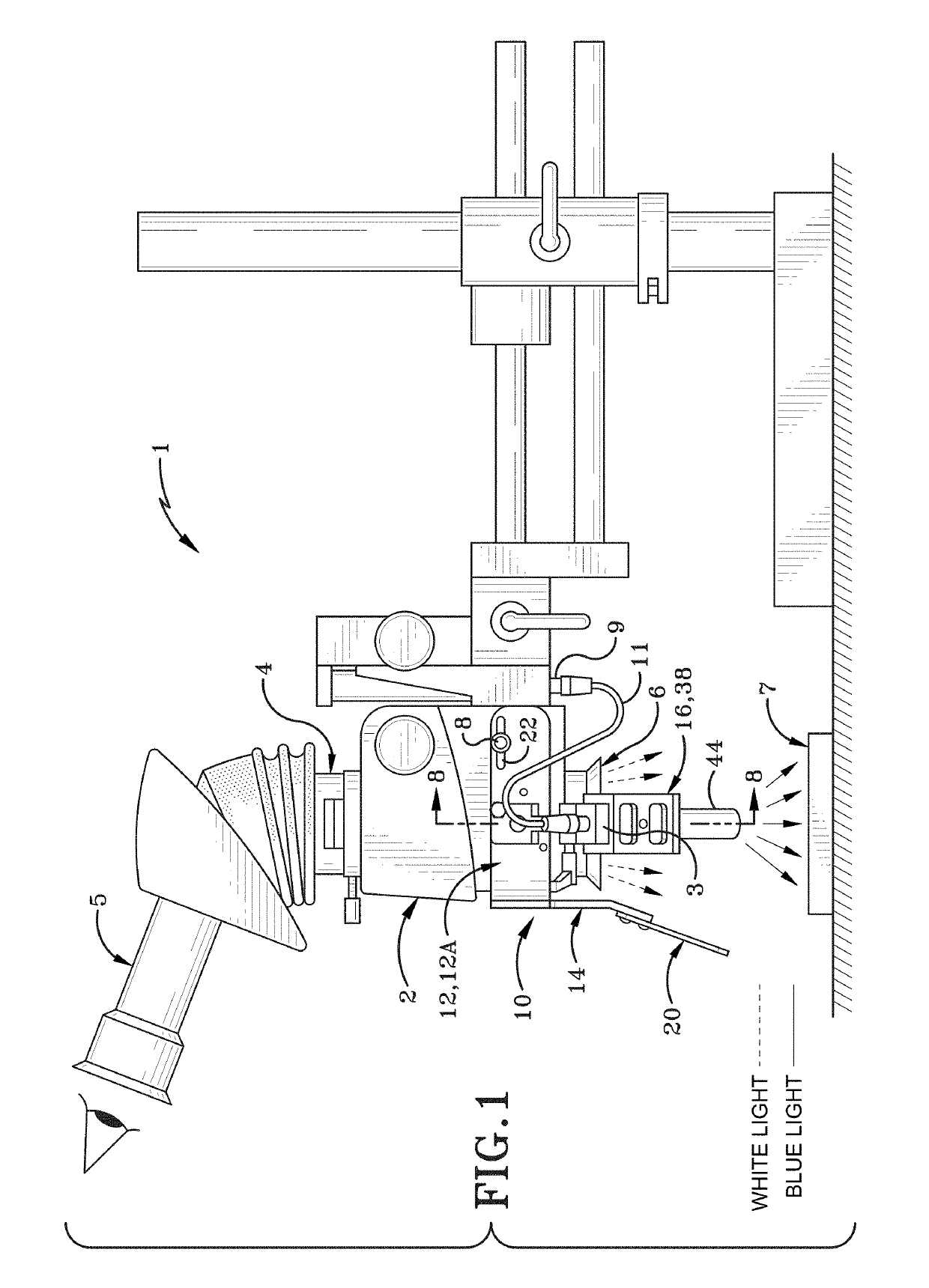
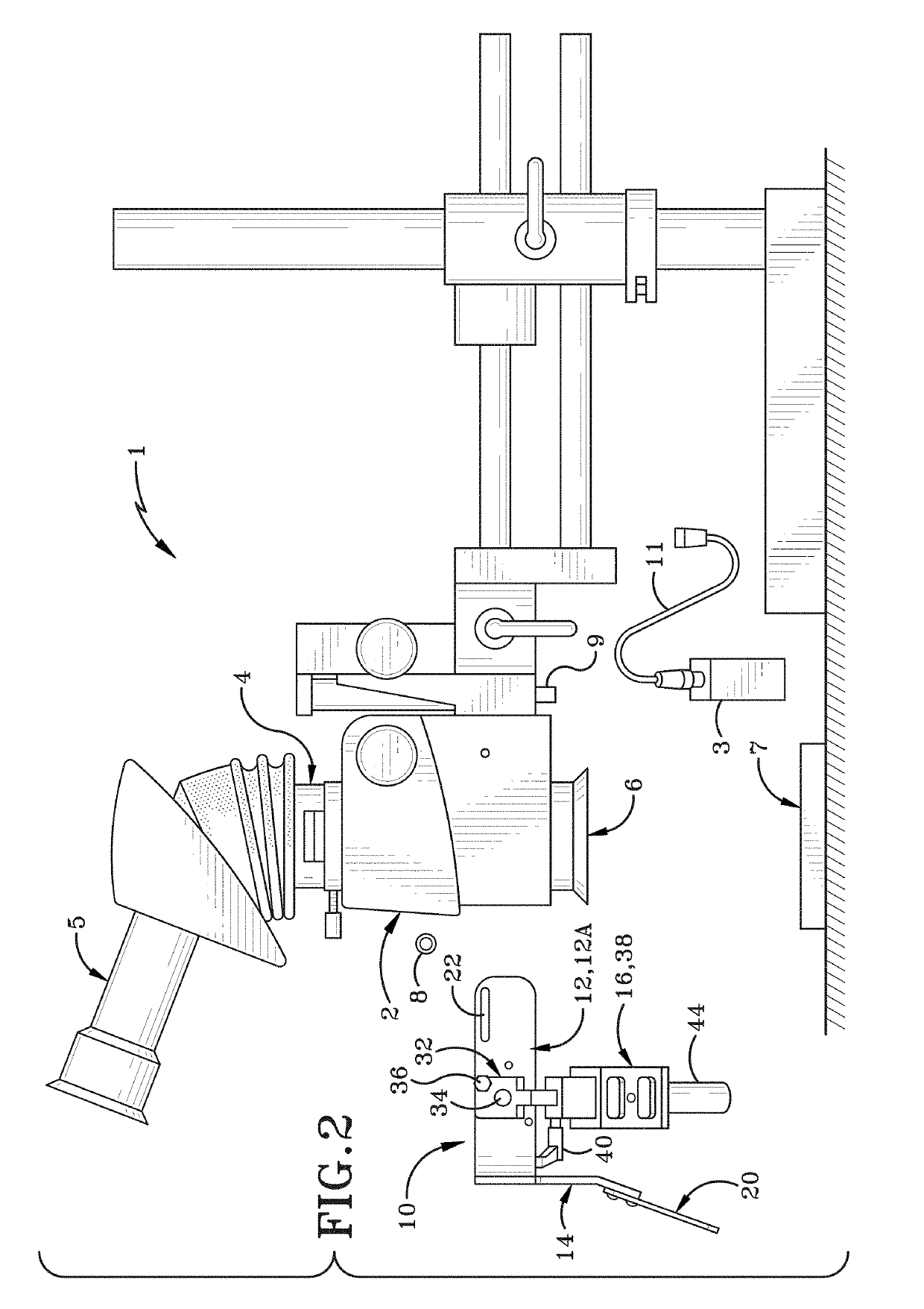
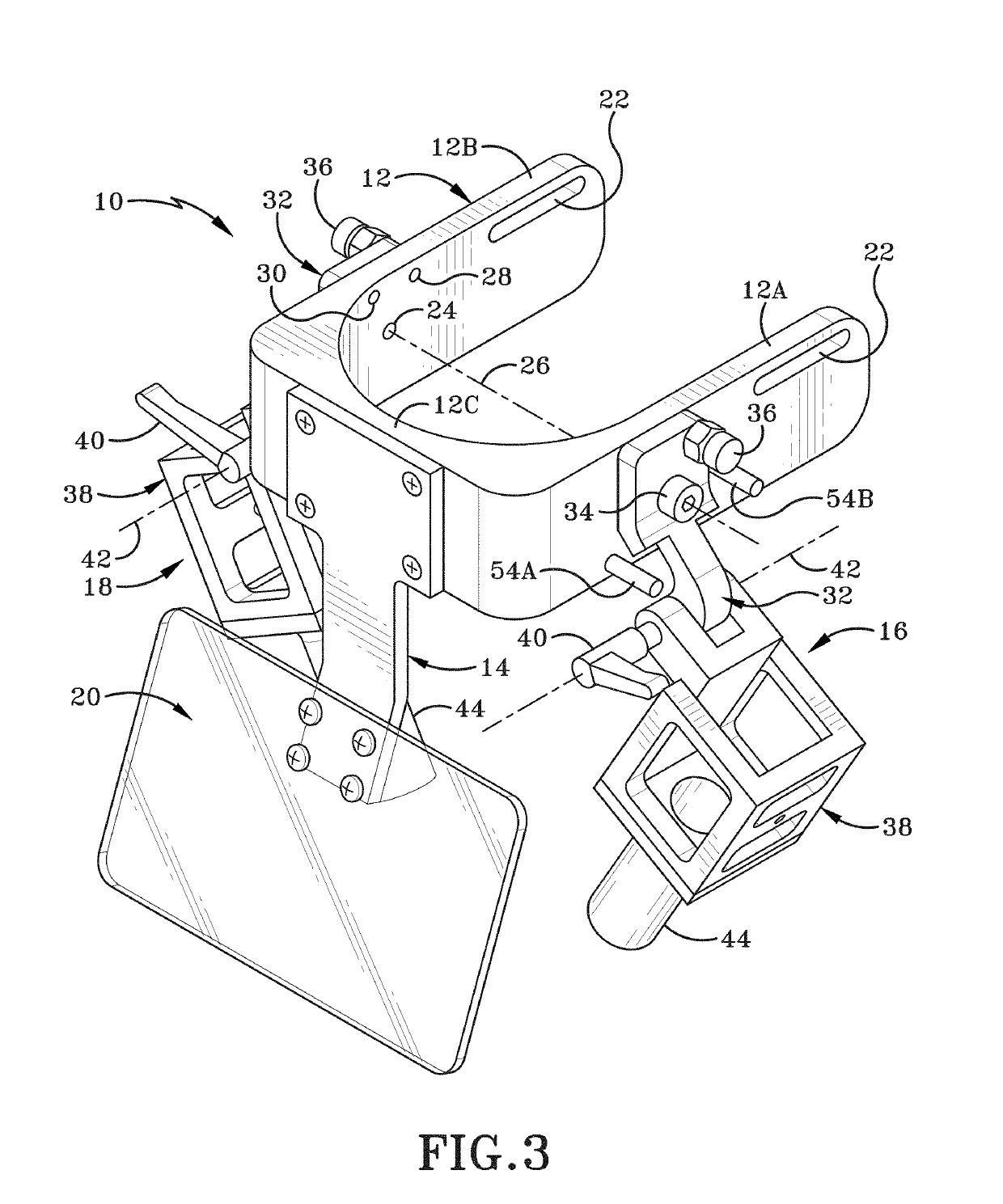
[0029]The present disclosure relates to an apparatus for holding a light source coupled with a viewing device to detect a contaminant on a microelectronic circuit board.

[0030]FIG. 1 and FIG. 2 depict a contaminant detection system 1 comprising a stereo microscope or other viewing device 2 equipped with a light source holding apparatus 10 and at least one blue light source 3 which has a wavelength in a range from about 400 nanometers (nm) to about 500 nm. The system 1 includes a filter 4 which is installed in a removably connected manner with the viewing device 2 between an eyepiece 5 and a white light source 6. The filter 4 is used to filter out any light which has a wavelength beyond a selected wavelength. In one example, the term “beyond” refers to filtering wavelengths shorter than the selected wavelength. A sample microelectronic circuit board 7 is placed under the blue light source 3 and white light source 6 of the microscope 2. As depicted in FIG. 2, the light source holding a...


PUM

PropertyMeasurementUnit
first wavelengthaaaaaaaaaa
fluorescent feedback second wavelengthaaaaaaaaaa

Abstract

The present disclosure relates to a system and method utilizing a light source coupled with a viewing device to detect contaminant(s) on an electronic circuit board. This fluorescence microscopy apparatus can be easily integrated into a bench top stereoscope or microscope and does not require the use of expensive and destructive analytical techniques. Typically, blue light is used in conjunction with a filter to detect contamination from cured epoxy resins and many other contaminants on gold bond pads, wires, pads, or other electrically conductive elements on the electronic circuit.

Description

BACKGROUNDTechnical Field[0001]The present disclosure relates generally to a method and system for detecting contaminants on a microelectronic circuit. More particularly, the present disclosure relates to a system and method of detecting contaminants on microelectronic circuits utilizing light in a first wavelength range that generates fluorescent feedback from a contaminant particle in a second wavelength range. More particularly, the present disclosure relates to the use of blue light to generate a fluorescent feedback from a contaminant particle coupled with a filter in a microscope or other viewing device that filters out the background blue light so as to only reveal the fluorescent feedback in the microscope or other viewing device.Background Information[0002]Microelectronic circuits or integrated circuits are small electrical devices configured to carry electrical current in the transmission of signals between electrical devices. The transmission of signals moving along the m...

Claims


Application Information

Patent Timeline
Patent Type & Authority Patents(United States)
IPC IPC(8): G01N21/64G02B21/24G01N21/94H01L21/02H01L21/66H01L21/67G02B21/00G01N21/88G02B21/16G02B5/20G01N21/956
CPCG02B21/16G01N21/8806G01N21/6447G01N21/8803G02B21/0016G02B21/24G01N21/94G02B5/208G01N2021/95638
Inventor ROCHFORD, RICHARDBALDWIN, TRISTAN J.BRABANT, JR., EDWARD L.MAZEL, CHARLES H.MEADE, MICHAEL J.
Owner BAE SYST INFORMATION & ELECTRONICS SYST INTERGRATION INC
Why Eureka
Try Eureka