Rotation driving apparatus, robot apparatus, control program, and article manufacturing method

a technology of rotating apparatus and robot arm, which is applied in the direction of programmed manipulators, programme control, instruments, etc., can solve the problems of affecting the operation accuracy affecting the degree of damage of the transmission, and affecting the accuracy of the operation of the robot arm, so as to achieve high speed

Active Publication Date: 2019-11-12
CANON KK
View PDF54 Cites 5 Cited by
  • Summary
  • Abstract
  • Description
  • Claims
  • Application Information

AI Technical Summary

Benefits of technology

[0009]The present invention aims to be able to detect accurately and at high speed the state of a transmission which is disposed in, e.g., a joint (rotation driving apparatus) of a robot.
[0011]According to such a constitution as described above, it is possible to detect the state of the transmission disposed in the joint of the robot accurately and swiftly, in accordance with the resonance amplitude of the joint measured via the output-side sensor of measuring the rotation angle of the output-side rotation shaft of the transmission. For this reason, there is a significant effect that it is possible to swiftly perform part exchange decision of the robot, and it is thus possible to maintain the joint (transmission) of the robot in an appropriate state.

Problems solved by technology

In the robot like this which can perform such complicated operations, since a degree of freedom of the operation by a robot arm is high, there is a possibility that the robot arm comes into contact with another object such as a workpiece, a tool or the like in a surrounding environment while the manufacturing work is being performed.
Thus, for example, if the robot arm comes into contact with a peripheral object or the like and thus a transmission (speed reducer) disposed in the joint of the arm is subject to impact, there is a fear that a breakdown (trouble) such as tooth skipping (tripping) or the like occurs in the speed reducer.
In the transmission (speed reducer) which uses the relevant strain wave gearing mechanism, since angle transmission accuracy of the joint deteriorates due to a breakdown such as tripping or the like, there is a possibility that operation accuracy of the robot arm resultingly deteriorates.
However, since it is difficult to visually confirm the transmission externally, it is substantially impossible to know the degree of damage of the transmission occurred by the contact.
Here, when knowing the damage by dismantling the transmission, it is necessary to remove the transmission from the robot arm, and thus there is a problem that it takes a lot of time to do so.
On the other hand, in the technique disclosed in Japanese Patent Application Laid-Open No. 2006-281421, since the value to be used for abnormality detection is obtained from the motor torque value, there is a problem that it is impossible to sufficiently obtain high detection accuracy because of the influence of the servo responsiveness of the arm itself.

Method used


Image

  • Rotation driving apparatus, robot apparatus, control program, and article manufacturing method
  • Rotation driving apparatus, robot apparatus, control program, and article manufacturing method
  • Rotation driving apparatus, robot apparatus, control program, and article manufacturing method

Examples


embodiment

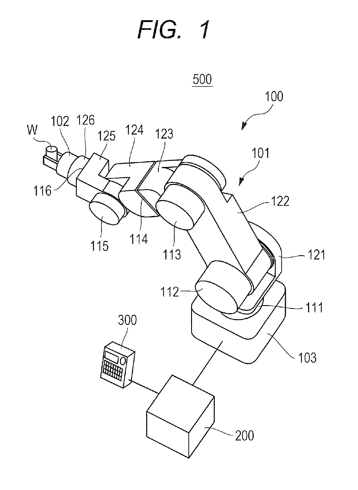
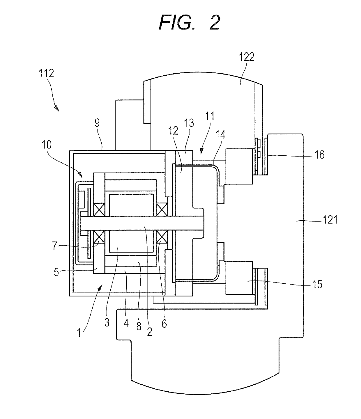
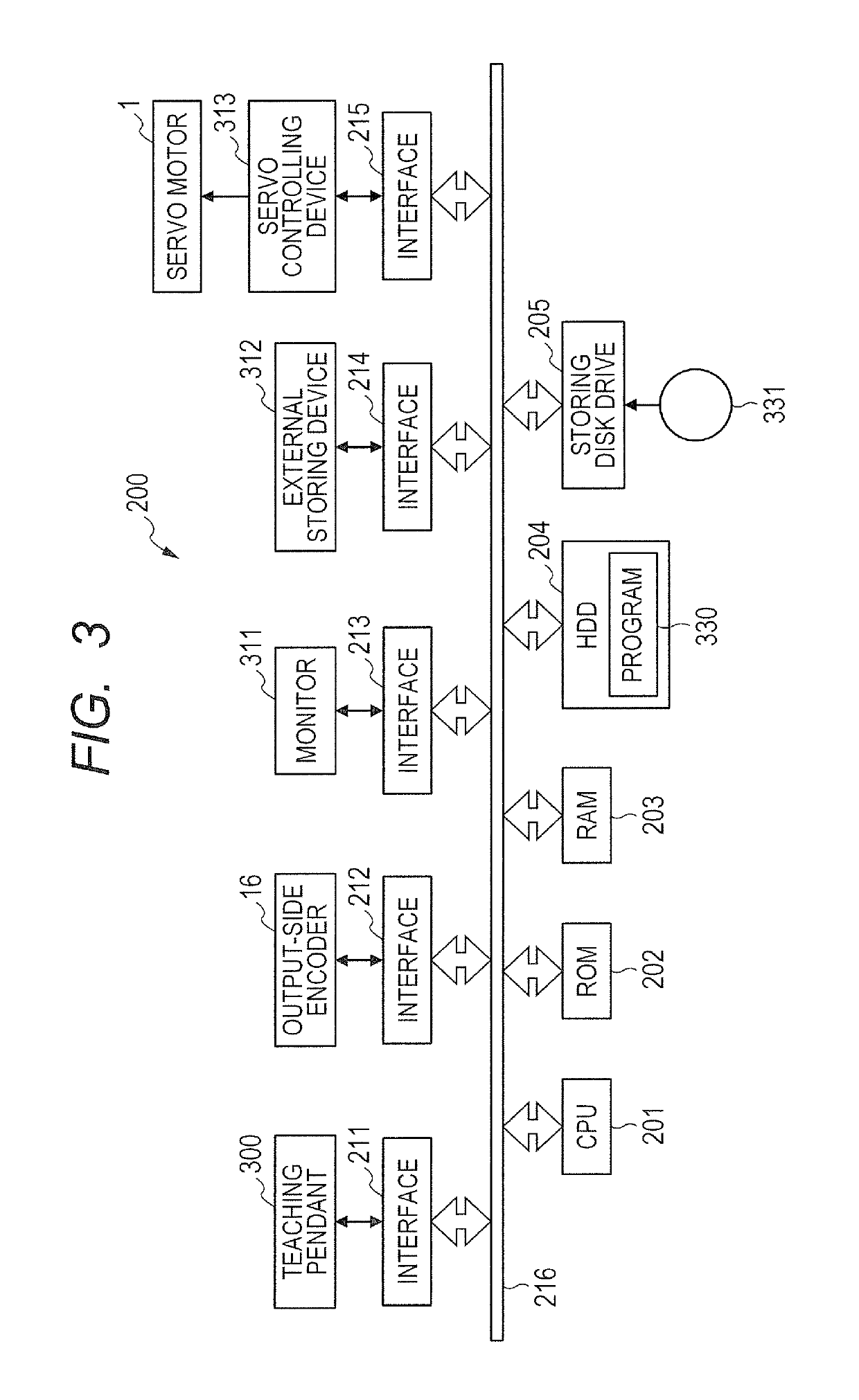
[0038]FIGS. 1 to 3 are the diagrams for illustrating an example of the constitution of a robot apparatus 500 to which the present invention can be carried out. More specifically, FIG. 1 is the diagram for schematically illustrating the entire constitution of the robot apparatus 500, FIG. 2 is the diagram for illustrating the section diagram of the constitution in the vicinity of one joint of the robot apparatus 500 of FIG. 1, and FIG. 3 is the diagram for illustrating the constitution of a controlling device 200 of the robot apparatus 500 of FIG. 1.

[0039]As illustrated in FIG. 1, the robot apparatus 500 comprises a robot 100 which assembles a workpiece W, the controlling device 200 which controls the robot 100, and a teaching pendant 300 which is connected to the controlling device 200. Besides, the controlling device 200 comprises a displaying unit (not illustrated) such as a monitor or the like.

[0040]The robot 100 comprises a six-shaft multi-joint robot arm 101, a hand (end effect...


PUM


Abstract

A joint of a robot comprises a servo motor, a speed reducer driven by the servo motor, and an output-side encoder for measuring a rotation angle of the output-side rotation shaft of the speed reducer, and the position / orientation of the robot is controlled by the joint. The present invention, which aims to be able to detect certainly and at a high speed the state of the speed reducer, is characterized by driving the joint via the speed reducer by rotating the servo motor, obtaining a resonance amplitude of the joint from the rotation angle obtained from the output-side encoder, and thus diagnosing the lifetime of the speed reducer according to the obtained resonance amplitude of the joint.

Description

BACKGROUND OF THE INVENTION[0001]Field of the Invention[0002]The present invention relates to a rotation driving apparatus which comprises a transmission driven by a rotation driving source, and an output-side sensor for obtaining a rotation angle of the output-side rotation shaft of the transmission, a robot apparatus which uses the rotation driving apparatus, a control program which is used for the rotation driving apparatus, and an article manufacturing method which is performed by the robot apparatus.[0003]Description of the Related Art[0004]In recent years, a producing (manufacturing) apparatus in which a multi-joint robot (simply called a robot hereinafter) is used becomes widespread in the field of industrial manufacturing. Here, the robot comprises, for example, a plurality of joints each driven by a rotation driving apparatus and thus enables to achieve complicated and high-speed article manufacturing work as with human hands. In the robot like this which can perform such c...

Claims


Application Information

Patent Timeline
Patent Type & Authority Patents(United States)
IPC IPC(8): B25J9/16
CPCB25J9/1651B25J9/1694G05B2219/37337G05B2219/37209G05B19/4065
Inventor TSUCHIYA, YUTAKA
Owner CANON KK
Why Eureka
Try Eureka