
Method of detecting FSK-modulated signals, corresponding circuit, device and computer program product

a technology of fsk-modulated signals and corresponding circuits, applied in the direction of dc level restoring means or bias distorting correction, baseband system details, instruments, etc., can solve the problems of complex circuits and intrinsic weakness in phase-variation, and achieve the effect of facilitating decoding of modulating signals

Active Publication Date: 2019-11-19
STMICROELECTRONICS INT NV
View PDF8 Cites 0 Cited by
  • Summary
  • Abstract
  • Description
  • Claims
  • Application Information

AI Technical Summary

Benefits of technology

[0014]robustness against phase jumps and possible frequency drifts, e.g., in the carrier signal which is FSK-modulated;
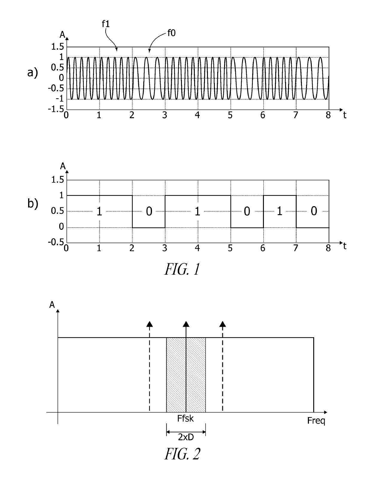
[0025]Consequently, operation of one or more embodiments may not be directly linked to the (absolute value of) the frequencies used, which facilitates decoding a modulating signal also in an MFSK scenario.
[0028]One or more embodiments may facilitate detecting a Qi signal (which is differentially encoded by using a bi-phase system), as well as a PMA signal based on the use of a Manchester code.

Problems solved by technology

Arrangements as discussed in the foregoing may suffer from various disadvantages including, e.g., circuit complexity (also in terms of a silicon area in the case of integrated circuits) and cost and exhibit an intrinsic weakness with respect to phase-variations (“jumps”) when transitioning from a frequency to another.

Method used


Image

  • Method of detecting FSK-modulated signals, corresponding circuit, device and computer program product
  • Method of detecting FSK-modulated signals, corresponding circuit, device and computer program product
  • Method of detecting FSK-modulated signals, corresponding circuit, device and computer program product

Examples


Embodiment Construction

[0037]In the ensuing description, one or more specific details are illustrated, aimed at providing an in-depth understanding of examples of embodiments of this description. The embodiments may be obtained without one or more of the specific details, or with other methods, components, materials, etc. In other cases, known structures, materials, or operations are not illustrated or described in detail so that certain aspects of embodiments will not be obscured.

[0038]Reference to “an embodiment” or “one embodiment” in the framework of the present description is intended to indicate that a particular configuration, structure, or characteristic described in relation to the embodiment is included in at least one embodiment. Hence, phrases such as “in an embodiment” or “in one embodiment” that may be present in one or more points of the present description do not necessarily refer to one and the same embodiment. Moreover, particular conformations, structures, or characteristics may be comb...


PUM


Abstract

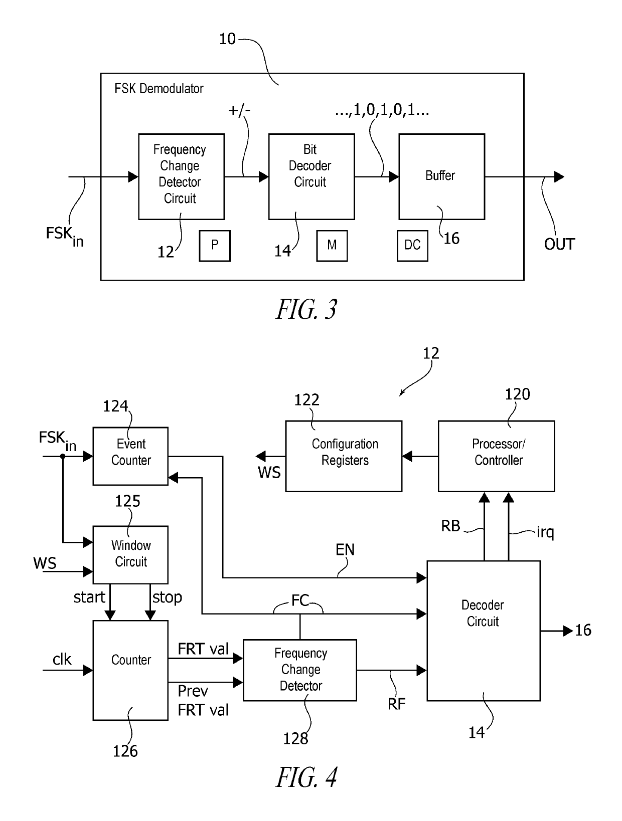
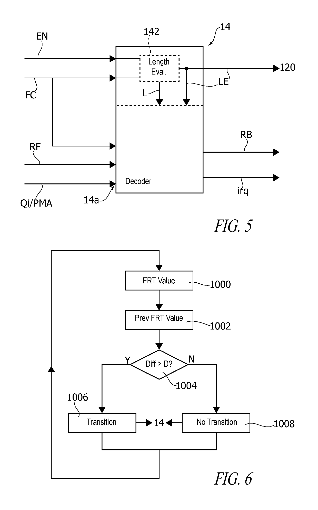
An occurrence of a first set of n periods of a frequency-shift-keying (FSK)-modulated waveform is counted, where n is an integer number. The n periods of the FSK-modulated waveform in the first set have a first time duration. An occurrence of a second set of n periods of the waveform is counted. The n periods of the waveform in the second set have a second time duration. The first time duration is determined based on the counting of the first set of n periods. The second time duration is determined based on the counting of the second set of n periods. A difference between the first time duration and the second time duration is compared to a threshold. Changes in frequency of the waveform are detected based on the comparing of the difference between the first time duration and the second time duration to the threshold.

Description

BACKGROUNDTechnical Field[0001]The description relates to detecting FSK-modulated signals.[0002]One or more embodiments may be applied to arrangements where information is exchanged between two devices. A “charger” device and a “charged” device exchanging information in order to regulate / adjust a charging process in, e.g., a wireless charger may be exemplary of such an arrangement.Description of the Related Art[0003]Frequency modulation (FM) involves a variation of the frequency of a modulated signal as a function of a modulating signal, such as, e.g., an information-carrying data signal.[0004]A common type of frequency modulation is Frequency Shift Keying (FSK). For instance, in two-level FSK (2-FSK) two different frequencies may correspond to two different binary levels (e.g., “0” and “1”).[0005]The frequency spectrum of the corresponding modulated signal includes a plurality of lines at locations dictated by the deviation frequency Δf and the modulation speed fc, as expressed e.g...

Claims


Application Information

Patent Timeline
Patent Type & Authority Patents(United States)
IPC IPC(8): H04L27/144G01R29/027H04L27/10H04L27/156H04L1/20H04L1/18H04L25/06
CPCG01R29/0273H04L27/144H04L27/1563H04L27/10H04L1/206H04L27/156H04L25/069H04L1/1835H04L27/12H04L27/14
Inventor DICOLA, EUSEBIOSALURSO, ELENAMILSIMER, JAN
Owner STMICROELECTRONICS INT NV
Learn More