
Method and apparatus for determining and using the sampling frequency for decoding watermark information embedded in a received signal sampled with an original sampling frequency at encoder side

a technology of sampling frequency and watermark information, which is applied in the direction of recording signal processing, television systems, instruments, etc., can solve the problems of difficult decoding of watermark information in received audio or video signals

Inactive Publication Date: 2014-04-01
MAGNOLIA LICENSING LLC
View PDF21 Cites 0 Cited by
  • Summary
  • Abstract
  • Description
  • Claims
  • Application Information

AI Technical Summary

Benefits of technology

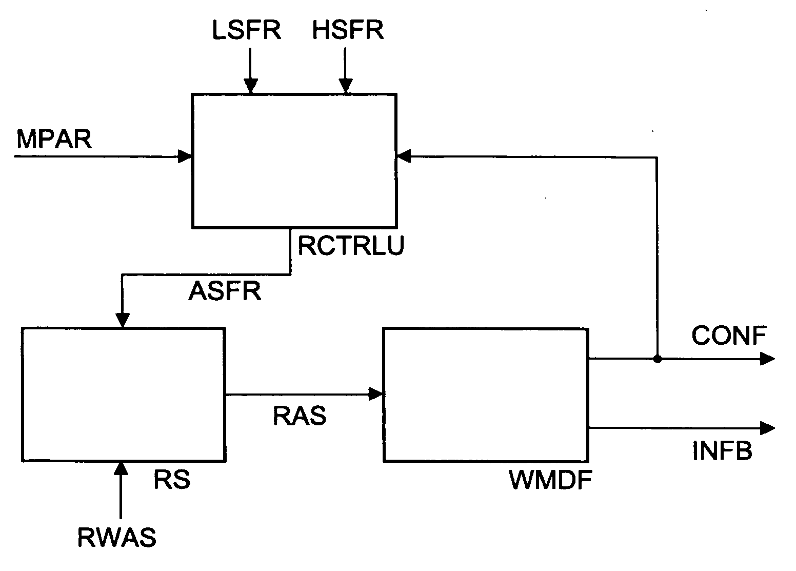
[0008]According to the invention, a re-sampler control unit controls the sampling frequency of a re-sampler, in connection with an audio watermark decoder. That watermark decoder outputs, in addition to the watermark information bits, a corresponding confidence value that is derived from a correlation result and that is used in the re-sampler control unit for synchronizing the re-sampler sampling frequency with the original sampling frequency of the incoming watermarked audio signal. The synchronization processing includes a ‘search mode’ and a ‘normal (i.e. synchronized) mode’. An advantage of the invention is that it facilitates decoding of watermarked signals starting with initially non-synchronized sampling frequencies.
[0009]In principle, the inventive method is suited for determining and using a sampling frequency for decoding watermark information embedded in a received signal sampled with an original sampling frequency at encoder side, said decoding including correlation with at least one reference pattern, said method including the steps:
[0011]for successive sections or frames of said received signal, scanning repeatedly candidate sampling frequencies within a frequency range that includes said original sampling frequency, thereby watermark decoding, using these candidate sampling frequencies, the corresponding section or frame of said received signal,
[0012]wherein for each candidate sampling frequency used in said watermark decoding a corresponding watermark bit confidence value derived from said correlation is determined and the confidence values for each one of the candidate sampling frequencies are summed up or combined,
[0013]and wherein, as soon as the confidence value of a current candidate sampling frequency is greater equal a first threshold value, said search mode is left and a normal mode is entered with this candidate sampling frequency being selected;
[0014]determining the maximum and the second maximum one of the confidence sum values wherein, as soon as their quotient or their difference exceeds a second threshold value, or in case a maximum scanning loop number is achieved, said search mode is left and said normal mode is entered upon selecting the candidate sampling frequency that is related to said maximum confidence sum value, or in case said maximum scanning loop number is achieved it is calculated whether said quotient or said difference exceeds said second threshold value and if not true said search mode is continued;

Problems solved by technology

However, receiving watermarked audio or video signals and watermark decoding them is difficult if the link between the watermark encoder and the watermark decoder is not a digital one.

Method used


Image

  • Method and apparatus for determining and using the sampling frequency for decoding watermark information embedded in a received signal sampled with an original sampling frequency at encoder side
  • Method and apparatus for determining and using the sampling frequency for decoding watermark information embedded in a received signal sampled with an original sampling frequency at encoder side

Examples


Embodiment Construction

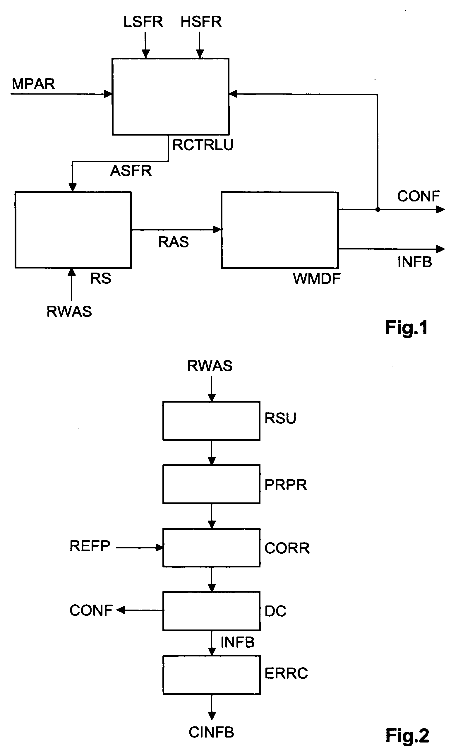
[0025]Most watermarking systems use a correlation based detection, which means that at encoder side several pseudo-random sequences representing a bit or word value are generated, or selected from a memory, and one or more of them are embedded inside the content or signal (e.g. an audio or video signal), depending on the message (e.g. watermark bits) to be embedded. The same pseudo-random sequences are generated, or selected from a memory, at decoder side. To decode the embedded message, it is necessary to determine which pseudo-random sequences were embedded inside the received content or signal. This is performed e.g. by correlating the known pseudo-random sequences with the possibly pre-processed content or signal. The decoder or receiver detector thereafter decides, depending e.g. on the size of the correlation result amplitude values, whether or not a given sequence was embedded.

[0026]In FIG. 1, for detecting the correct sampling frequency of the incoming watermarked signal RWA...


PUM


Abstract

In watermarked signal decoding, the embedded message is decoded by correlating the reference patterns with the watermarked signal. The watermark detector decides, depending on the size of the correlation result values, whether or not a given reference pattern was embedded. However, decoding watermarked audio or video signals is difficult if the link between the watermark encoder and the watermark decoder is not a digital one, for example an acoustic path. A re-sampler control unit controls the sampling frequency of a re-sampler, in connection with a watermark decoder that outputs, in addition to the watermark information bits, a corresponding confidence value that is derived from the correlation result and that is used for synchronizing the re-sampler sampling frequency with the original sampling frequency of the watermarked signal. The synchronization processing includes a search mode and a synchronized mode.

Description

[0001]This application claims the benefit, under 35 U.S.C. §119, of European Patent Application No. 08100898.9 of 24 Jan. 2008.FIELD OF THE INVENTION[0002]The invention relates to a method and to an apparatus for determining and using at decoder side the sampling frequency for decoding watermark information embedded in a received signal sampled with an original sampling frequency at encoder side.BACKGROUND OF THE INVENTION[0003]A watermark in an audio or video signal can be detected at receiving or decoder side using correlation, as described for example in WO 2007 / 031423, WO 97 / 33391 (U.S. Pat. No. 6,584,138 B1) or U.S. Pat. No. 6,061,793.[0004]Many watermarking systems make use of correlation for calculating a detection metric, which means that several pseudo-random sequences or reference patterns are generated, or read from a memory, at encoder side and one or more of them are embedded inside the content (e.g. an audio or video signal), dependent on the message to be embedded. No...

Claims


Application Information

Patent Timeline
Patent Type & Authority Patents(United States)
IPC IPC(8): H04N7/167H03M1/06H04L29/06G10L19/018H04L9/32G10L19/00
CPCH03M1/0617H04N7/167G06T1/005G06T2201/0065G06T2201/0052G11B20/00884H04L9/3247G10L19/018H04L9/32H04N21/4394H04N21/8358
Inventor BAUM, PETER GEORGVOESSING, WALTERGRIES, ULRICH
Owner MAGNOLIA LICENSING LLC
Learn More