Component and production method

a technology of components and production methods, applied in the field of components, can solve the problems of residual stresses, inability to move, and irregularity of panel-shaped pieces, and achieve the effects of easing the loosening of extending the connection of pieces, and permanent overturning the gap

Active Publication Date: 2019-11-26
SCHILCHER JOSEF
View PDF34 Cites 1 Cited by
  • Summary
  • Abstract
  • Description
  • Claims
  • Application Information

AI Technical Summary

Benefits of technology

[0027]Due to the inventive design of the component, on the one hand, and of the method according to the invention, on the other hand, it is effectively possible to tension the pieces together and to permanently overcome a gap. This also applies if there are tongues and grooves in the narrow surfaces of the pieces, so that the pieces are aligned flush with one another.
[0028]In one embodiment of the invention, it can be provided that in at least one part of the connecting elements, there is anchoring on which a tool can be attached for pulling out the part. This facilitates the loosening of the connection of pieces. The anchoring can be made in the form of metal sleeves with a (woodworking) thread provided outside and a thread provided inside, into which a tool can be screwed. For example, the sleeves are so-called “RAMPA” sleeves.

Problems solved by technology

The design of the profile rods, on the one hand, and the design of the coupling rods of FR 1 518 263 A, on the other hand, do not make it possible to move, for example, panel-shaped pieces onto one another during connection.
Ceilings and similar components that consist of prefabricated pieces in the form of panel-shaped ceiling elements and that are generally only joined together at the construction site often have residual stresses and are not straight.
The tensioning of these pieces together to form a gapless component is time-consuming and requires mechanical clamping devices.
This type of connection has the disadvantage that the pieces that are to be connected to one another can only be held in their uppermost region by the facing board using screws and the components can open to the inside by a gap being formed there again.
This is disadvantageous since wooden ceilings and other components are being increasingly used as decorative ceilings or decorative components in which gaps are perceived as disruptive.

Method used


Image

  • Component and production method
  • Component and production method
  • Component and production method

Examples


Embodiment Construction

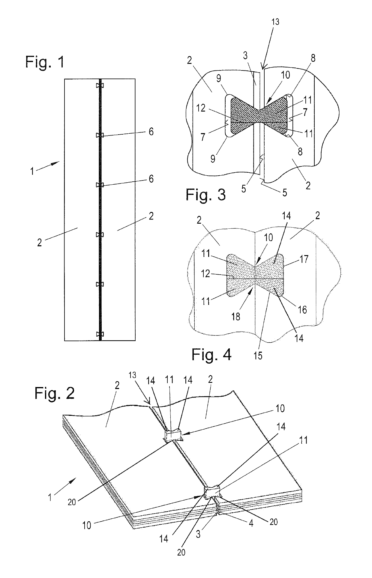
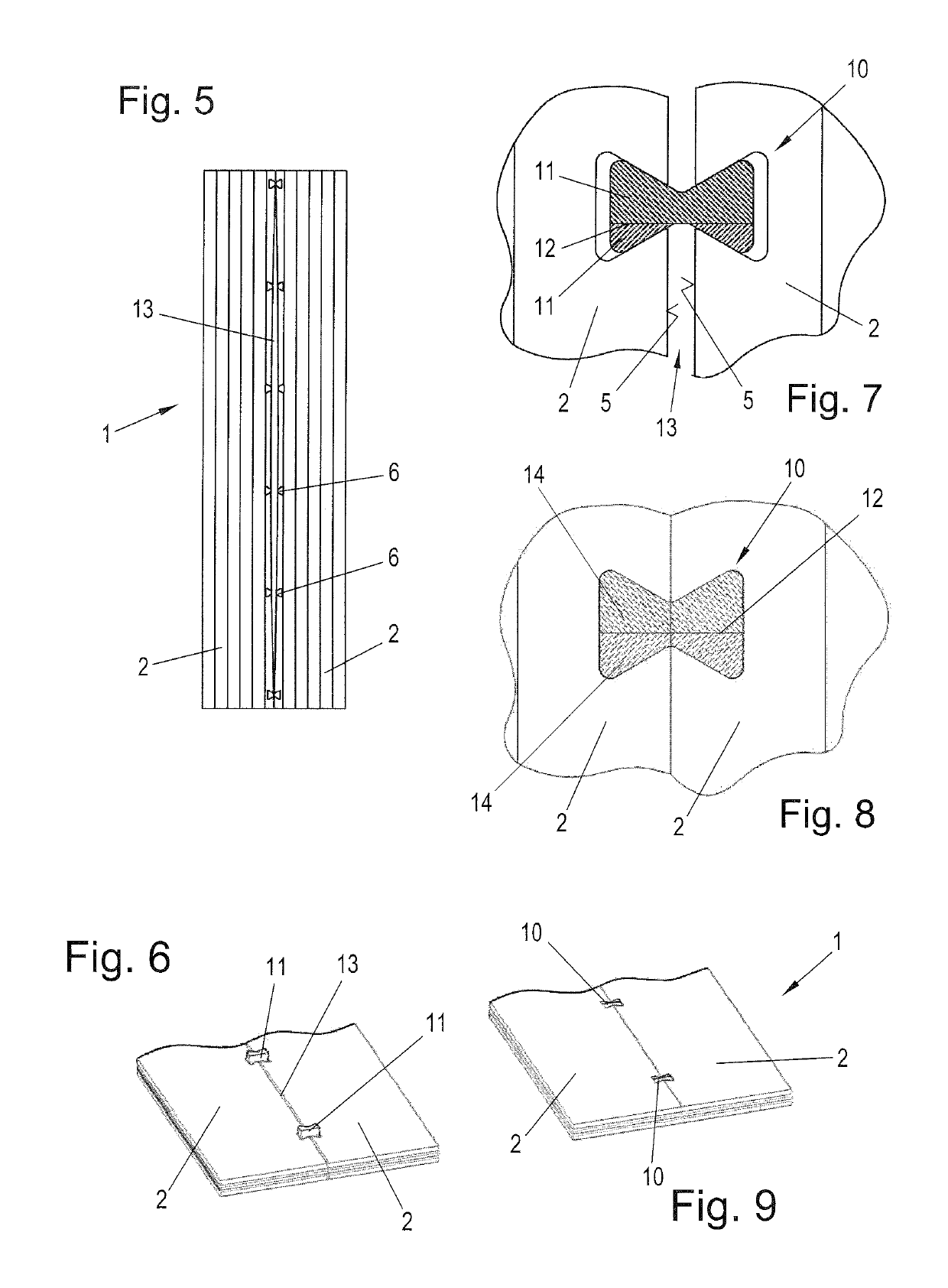
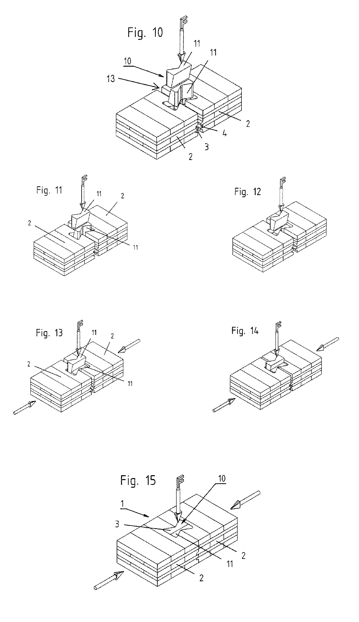
[0043]A component 1 (not yet completed) that is shown schematically in FIG. 1 and that is, for example, a component for a ceiling comprises two pieces 2 (ceiling elements) that are facing one another via their narrow surfaces 5. In the narrow surfaces 5, in one piece 2 there is a groove 4 and in the other piece 2 there is a tongue 3 (FIG. 2). The tongue 3 can be a self-contained tongue or an outside tongue.

[0044]In the pieces 2 in the region of the narrow surfaces 5, there are recesses 6 that are made undercut; therefore, they each have a base 7 that is wider than the mouths of the recesses 6 that lie in the narrow surfaces 5 of the pieces 2.

[0045]In order to connect the pieces 2 to one another to form the component 1, connecting elements 10 are inserted into the recesses 6. Each of the connecting elements 10 consists of two wedge-shaped parts 11 that adjoin one another via their facing wedge surfaces 12. The wedge-shaped parts 11 of the connecting elements 10 are abutted such that ...


PUM


Abstract

A component having at least two parts which contact one another via their narrow faces, includes multiple connection elements which pretension the parts with respect to one another. The connection elements are accommodated in recesses formed as undercuts in the parts. The recesses are aligned transversely to the longitudinal extension of the narrow faces of the parts, the openings of the recesses being open towards the narrow faces of the parts. The connection elements are respectively formed of two wedge-shaped pieces arranged in a diametrically opposed manner. When the pieces of the connection elements are accommodated completely in the recesses, the ribs of the connection elements completely fill out the recesses, so that the parts are pretensioned with respect to one another, and a gap is prevented from forming between the parts or the closing of a previously present gap is achieved.

Description

BACKGROUND OF THE INVENTIONField of the Invention[0001]The invention relates to a component comprising at least two pieces that adjoin one another over one of their surfaces and at least one connecting element that holds the pieces in their adjoining position.[0002]The invention furthermore relates to a method for producing a component according to the invention.[0003]Components of the initially-named type are known in various embodiments.Description of the Related Art[0004]Reference is made to FR 1,570,606 A, AT 12 597 U1, EP 2 264 323 B1 and U.S. Pat. No. 1,985,992 A. These documents disclose components in which the connecting means have two widening ribs that are opposite one another and that are inserted into longitudinally-running grooves that are made undercut in the adjoining narrow surfaces of the pieces.[0005]Similar pieces are known from AT 505 737 B1 and WO 2014 / 153574 A1. In order to simplify the assembly and the tensioning of the pieces together to form the component, t...

Claims


Application Information

Patent Timeline
Patent Type & Authority Patents(United States)
IPC IPC(8): E04B1/61F16B5/00E04B2/02E04B2/08E04B1/10
CPCE04B1/61F16B5/0088E04B1/10E04B2/08E04B1/6162F16B5/0056E04B2002/0252E04B1/6158F16B5/0052
Inventor SCHILCHER, JOSEF
Owner SCHILCHER JOSEF
Why Eureka
Try Eureka