Capillary array

a capillary array and capillary technology, applied in the field of capillary arrays, can solve the problems of complicated optical measurement perpendicular to the longitudinal axis of the capillary, and achieve the effect of convenient manual handling and advantageous automation

Active Publication Date: 2019-11-26
NANOTEMPER TECH GMBH +1
View PDF11 Cites 0 Cited by
  • Summary
  • Abstract
  • Description
  • Claims
  • Application Information

AI Technical Summary

Benefits of technology

[0019]By using the array of the invention together with the tray of the invention, for example 4×24=96 capillaries / samples may be measured very easily and fast, i.e., significantly fewer steps are required compared to the known method with single capillaries. For example, when filling and putting down 96 individual capillaries from a multiwell plate (1× filling+1× putting down=2 steps) 2×96=192 individual steps would be needed. When using 4 arrays, each comprising 24 capillaries (4×24=96), for filling and putting down merely 2×4=8 steps are required; the effort vis-à-vis 96 individual capillaries is thus reduced to 8 / 192*100%=4%, an improvement by the factor of 25. The array may be handled more easily than individual capillaries and protects the capillaries from mechanical damages and contaminations, for example fingerprints, which may disturb the optical measurements for example by their autofluorescence, which significantly increases process safety. The array prevents the individual capillaries from being mixed up and / or commutated and allows a preferably unambiguous traceability / documentation / allocation of samples to be examined to capillaries and carrier by a preferably unambiguous marking, which is advantageous for diagnostic applications and analytical applications as for example drug research or drug formulation.
[0071]Light transmission of the segment allows carrying out measurements of luminescence / fluorescence / phosphorescence and / or optical examinations / measurements (for example interference, polarisation, absorption, dichroism, ellipsometry, anisotropy, Raman, microscopy, dark field, light diffusion, FRET) and / or manipulations of the solution / liquid and / or the gas (fluid) in the well of the tube-like structure. Light transmission can further allow carrying out fluorescence measurements. According to a preferred embodiment light transmission also enables the heating of fluids in the tube-like structure by means of electromagnetic radiation, for example light (preferably a infrared (IR) laser), preferably the heating of water and / or organic solvents.

Problems solved by technology

Further, the array on which the capillaries are attached or fixed should not be completely impervious or opaque to light since in this way an optical measurement perpendicular to the longitudinal axis of the capillary may be complicated.

Method used


Image

  • Capillary array
  • Capillary array
  • Capillary array

Examples


Embodiment Construction

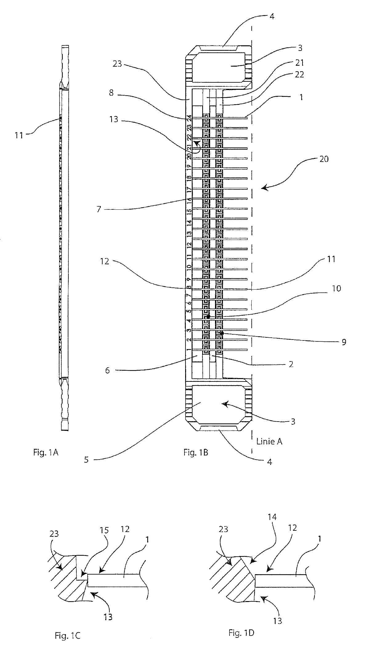
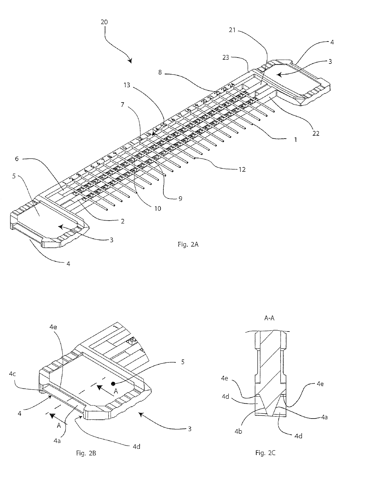
[0147]FIG. 1B schematically shows an exemplary embodiment of an array 20 according to the present invention in a top view. 24 capillaries 1 with a consistent distance of about 4.5 mm are attached to the array in a common plane, wherein the common plane lies parallel to or in the paper plane. In particular, the common plane is visible in the side view of FIG. 1A. The array has substantially two, preferably approximately parallel mounting struts 21, 22. Preferably, each capillary 1 is attached / fixed to both mounting struts, i.e. each capillary is mounted to the array at least at two points 9, 10 being spaced apart from each other, which enables a secure mounting. Preferably, both mounting struts 21, 22 are being spaced apart from each other. Preferably, the measuring slot / the measuring window 2, which enables light to be transmitted through the individual capillaries perpendicular to the common plane, is positioned between both mounting struts. For example, the measuring slot / measurin...


PUM

PropertyMeasurementUnit
distanceaaaaaaaaaa
distanceaaaaaaaaaa
heightaaaaaaaaaa

Abstract

The invention relates to arrays with a plurality of capillaries being arranged in a plane and mechanically attached to the array, wherein the distance of adjacent capillaries is approximately 2.25 mm or an integer multiple thereof. At least one free end of each capillary projects from the array in such a way that the free ends of the capillaries may be simultaneously inserted into wells of a microwell plate.

Description

[0001]The present invention generally relates to a capillary array. In particular, the invention relates to an array for a plurality of capillaries by means of which a simultaneous filling of a plurality of capillaries of a microwell plate is made possible. Furthermore, the invention also relates to an apparatus and a method for filling, transportation and measurement of fluids having volumes at microlitre levels.BACKGROUND OF THE INVENTION[0002]NanoTemper Technologies GmbH develops and sells measurement devices, by means of which liquids within a capillary are examined or analyzed optically. It is further known that a single capillary is taken by hand, immersed into a liquid and then separately put down on an array and subsequently pushed into the measuring device. The individual filling is advantageous for certain single samples, however, if larger amounts of samples are to be examined, said method requires many steps which cannot readily be automated.[0003]Application no. EP 2 57...

Claims


Application Information

Patent Timeline
Patent Type & Authority Patents(United States)
IPC IPC(8): G01N21/03G01N21/71B01L9/06G01N21/13G01N21/11B01L7/00
CPCG01N21/03G01N21/11B01L9/065G01N21/13G01N21/71G01N2201/04B01L2400/0406B01L7/00B01L2300/0838G01N2201/02
Inventor BAASKE, PHILIPPDUHR, STEFANREICHL, STEFANBIGUS, HANS-JURGEN
Owner NANOTEMPER TECH GMBH
Why Eureka
Try Eureka