Inner-rotor-type motor and electric tool provided with same

a technology of inner-rotor-type motors and electric tools, which is applied in the direction of stator/rotor bodies, magnetic circuit shapes/forms/construction, and association with control/drive circuits. it can solve the problems of vibration due to the environment or the operation of the motor, and compromising the durability of the sensor substrate. , to achieve the effect of reducing the axial thickness of the insulator, reducing the radial thickness of the housing

Active Publication Date: 2019-11-26
PANASONIC INTELLECTUAL PROPERTY MANAGEMENT CO LTD
View PDF13 Cites 1 Cited by
  • Summary
  • Abstract
  • Description
  • Claims
  • Application Information

AI Technical Summary

Benefits of technology

[0011]With the configuration described above, the projecting portion of the housing is fitted into the recess portion of the stator, which makes it impossible for the stator to make a relative movement in the axial direction with respect to the housing, and thus the stator can be positioned with respect to the housing. Also, because the housing has the projecting portion on its inner circumferential surface, in a portion of the housing excluding the projecting portion, the radial thickness of the housing can be reduced. Furthermore, because the recess portion of the stator is configured by a first end surface of the stator core and a cutout portion formed in the insulator, it is possible to reduce the axial thickness of the insulator. This is because with the configuration described above, the recess portion of the stator is provided on a second end surface side of the insulator. In the case where, as in PTL 1, the recess portion of the stator is provided at the center of the insulator, as described above, in two regions that are on opposing sides of the recess portion, the insulator needs to have a certain degree of thickness or more. In contrast, with the configuration described above, in order to maintain the strength of the insulator, it is only necessary to configure the insulator to have a certain degree of thickness or more in only one region between an end surface that is opposite to the second end surface and the cutout portion. Accordingly, as compared with the configuration in which the recess portion of the stator is provided at the center of the insulator, the axial thickness of the insulator can be reduced. As a result, it is possible to prevent an increase in the size of the inner-rotor-type motor in both the radial direction and the axial direction.

Problems solved by technology

However, if the sensor substrate is attached directly to the housing, a problem arises in that the durability of the sensor substrate is compromised.
For example, if a motor as described above is used as the power source in an electric tool such as an impact driver, vibration occurs due to the environment or the operation of the motor itself.
The vibration causes a stress concentration in the attachment portion where the sensor substrate and the housing are attached, which may compromise the durability of the sensor substrate.
This is to prevent the accuracy of positioning of the sensor substrate from lowering due to an error in the axial length of the stator core.

Method used


Image

  • Inner-rotor-type motor and electric tool provided with same
  • Inner-rotor-type motor and electric tool provided with same
  • Inner-rotor-type motor and electric tool provided with same

Examples


embodiment

[0020]Hereinafter, an embodiment of the present invention will be described with reference to the drawings.

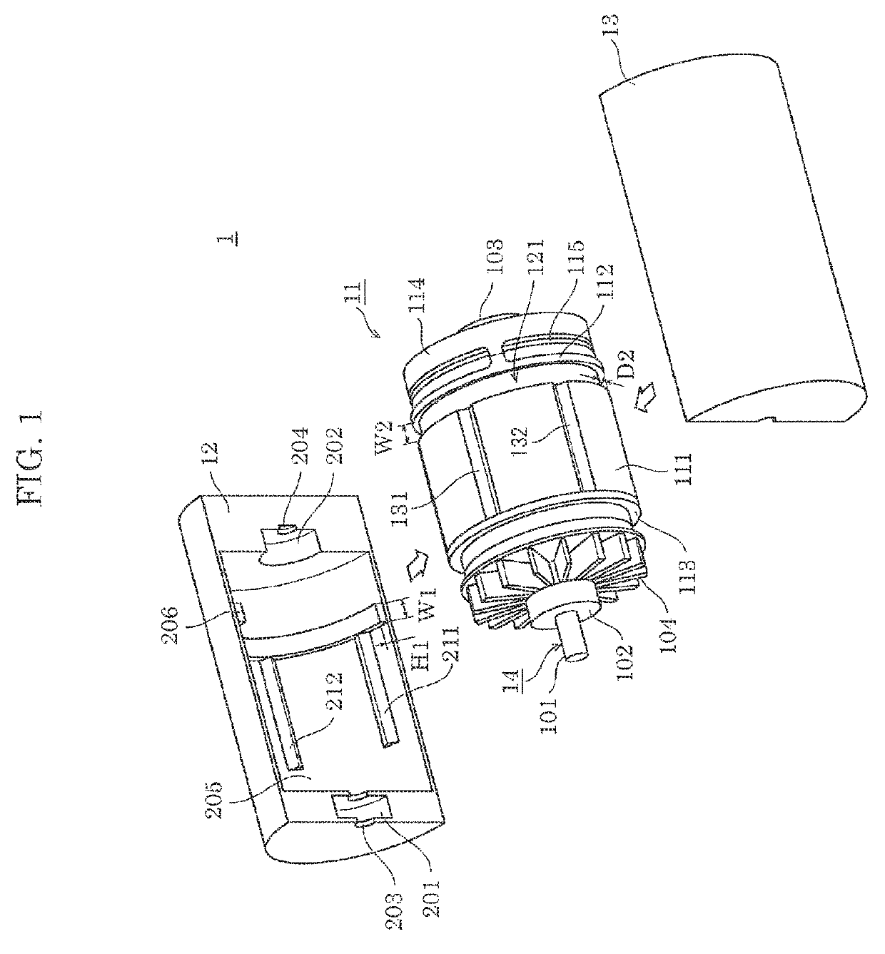
[0021]FIG. 1 is an exploded perspective view of DC brushless motor 1 according to the embodiment. As shown in FIG. 1, its housing has a structure that is split along an axially extending split surface into two lateral parts and thus is composed of first half casing 12 and second half casing 13. First half casing 12 and second half casing 13 are coupled by, for example, a faster such as a combination of a bolt and a nut, an engagement structure such as a combination of an engagement claw and an engagement recess portion that mates with the engagement claw, or an adhesive.

[0022]Stator 11 includes stator core 111, insulator 112, insulator 113, heat dissipator 114, and sensor substrate 115. In stator 11 shown in FIG. 1, rotor 14 including shaft 101 and cooling fan 104 is provided inside stator 11 by being supported by bearing 102 and bearing 103.

[0023]Stator core 111 and insulator ...


PUM


Abstract

An inner-rotor-type motor is configured such that a projecting portion is formed on an inner circumferential surface of a housing, a recess portion is formed on an outer circumferential surface of a stator, the stator is positioned with respect to the housing by the recess portion and the projecting portion being fitted to each other, the stator is configured by an annular insulator having an attachment surface being brought into close contact with a core end surface at one axial end of a stator core, a sensor substrate is attached to the insulator so as to be capable of detecting a rotation angle of a rotor, the recess portion of the stator is configured by a cutout portion being formed in an area that is a part of an outer circumferential surface of the insulator and includes a portion that is brought into close contact with the core end surface.

Description

RELATED APPLICATIONS[0001]This application is the U.S. National Phase under 35 U.S.C. § 371 of International Patent Application No. PCT / JP2015 / 005618, filed on Nov. 11, 2015, which in turn claims the benefit of Japanese Application No. 2014-241629, filed on Nov. 28, 2014, the disclosures of which Applications are incorporated by reference herein.TECHNICAL FIELD[0002]The present invention relates to an inner-rotor-type motor and an electric tool provided with the inner-rotor-type motor.BACKGROUND ART[0003]In general, an inner-rotor-type motor includes a housing, a stator fixed to the housing, and a rotor provided in the stator. In particular, in a motor in which the rotor is a permanent magnet, a magnetic pole strength generated by the stator is controlled by detecting the magnetic pole position of the rotor in order to prevent a step-out and a synchronization loss. For this purpose, such a motor includes a sensor substrate on which a magnetic sensor such as a hall element is mounted...

Claims


Application Information

Patent Timeline
Patent Type & Authority Patents(United States)
IPC IPC(8): H02K5/16H02K29/08H02K1/18H02K3/34H02K11/21H02K11/30H02K5/08H02K5/15H02K21/16H02K5/04H02K5/14H02K15/02H02K15/03H02K21/14
CPCH02K5/163H02K1/18H02K3/34H02K5/08H02K5/15H02K11/21H02K11/30H02K21/16H02K29/08H02K5/04H02K5/14H02K5/16H02K15/028H02K15/03H02K21/14H02K9/06H02K1/185H02K11/215H02K11/33H02K2211/03
Inventor KITAMURA, KOTATSUBAKIMOTO, HIROYUKIOISHI, RYOHEI
Owner PANASONIC INTELLECTUAL PROPERTY MANAGEMENT CO LTD
Why Eureka
Try Eureka