

Suturing devices for heart valve surgery
- Summary
- Abstract
- Description
- Claims
- Application Information
AI Technical Summary
Benefits of technology
Problems solved by technology
Method used
Image

Examples
Embodiment Construction
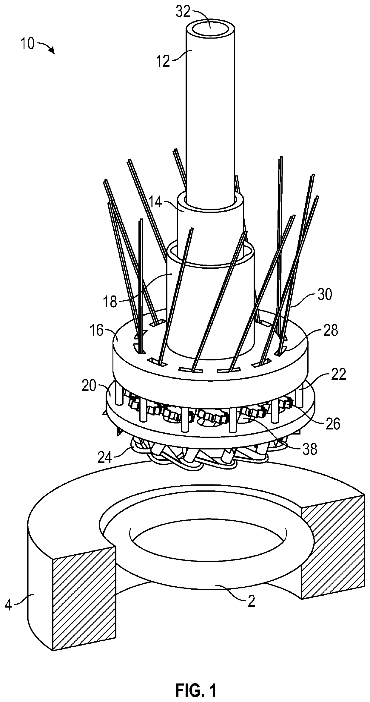
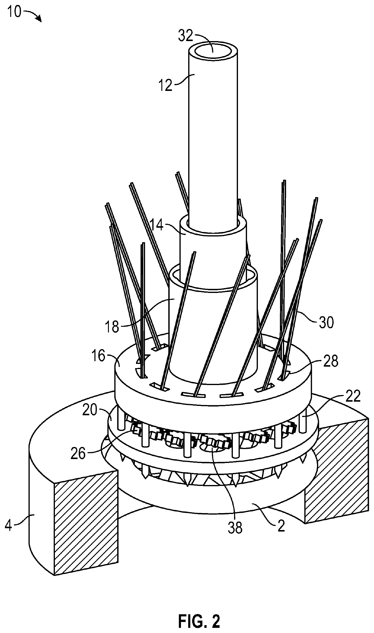
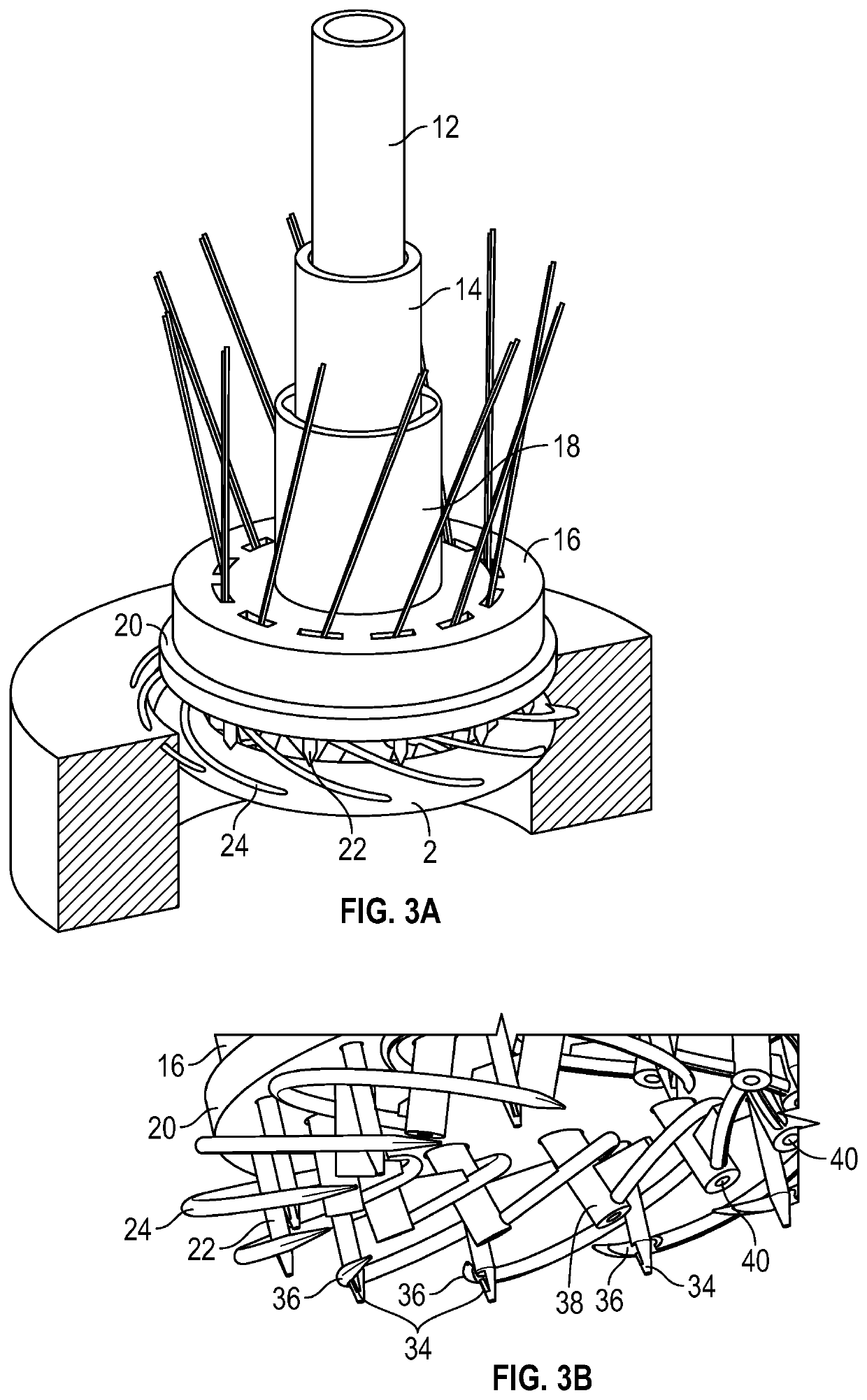
[0035]FIGS. 1, 2, 3A, and 4 show an annular prosthetic device 2 positioned at a desired position within the walls of a native heart valve region 4. Although the illustrated annular prosthetic device 2 is shown as a toroidal ring, it is intended to represent any of various possible annular prosthetic devices that may be sutured in place using the disclosed technology. In the case of implanting a prosthetic heart valve, for example, the illustrated annular prosthetic device 2 can represent an outer sewing ring of the prosthetic heart valve. In other procedures, the illustrated annular prosthetic device 2 can represent a flat annuloplasty ring or similar devices. Similarly, although the native heart valve region 4 is shown in FIGS. 1, 2, 3A, and 4 as a cut-away ring with a cylindrical inner wall, it is intended to represent the actual geometry of a native heart valve region (e.g., aortic valve region, pulmonary valve region, tricuspid valve region, or mitral valve region), which includ...
PUM
 Abstract
Description
Claims
Application Information