
Double effect hydraulic actuating cylinder

a hydraulic actuating cylinder and double-action technology, which is applied in the direction of propulsive elements, vessel construction, steering rudders, etc., can solve the problems of loss of seal between the cylinder and the rod, difficulty in disassembling the rod from the bracket fastening the cylinder to the engine, etc., and achieves greater strokes of the cylinder on the rod, better protection against salt, and increased protection

Active Publication Date: 2019-12-03
ULTRAFLEX
View PDF12 Cites 0 Cited by
  • Summary
  • Abstract
  • Description
  • Claims
  • Application Information

AI Technical Summary

Benefits of technology

[0014]Purpose of this invention is to implement a simple and inexpensive measure which allows the problem to be at least partially solved.
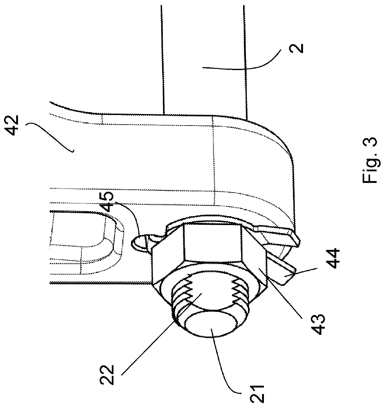
[0016]Preferably, the flattened surface is obtained in proximity of at least one, preferably both, the opposite ends of the rod. In this way, an ad hoc area for grasping the rod is created in at least one region not involved in the cylinder sliding, thereby facilitating the disassembly of the bracket without the risk of damaging the rod.
[0022]In an embodiment, the distance of the flattened surface from the end of the rod is such that, when the bracket is mounted on the rod, the flattened surface is positioned within the thickness of the end element of the bracket. This can be achieved, for example, by using an annular shoulder abutting the end of the rod. In this way, better protection against salt is provided in both the threaded region and the region weakened by the flattened surface, and greater strokes of the cylinder on the rod are allowed.
[0023]The protection can be increased even more by obtaining, on the rod in a backward position with respect to the flattened surface, an annular groove for the insertion of a sealing ring. Advantageously, the flattened surface has such a longitudinal extent to be at least partially enclosed in the thickness of the end element of the bracket in order to ensure the seal.

Problems solved by technology

Although these devices perform their function satisfactorily, they have some drawbacks.
One of the most common drawbacks is the difficulty of disassembling the rod from the bracket fastening the cylinder to the engine.
On the other hand, the grip of this tool can damage the surface of the rod, resulting in a loss of seal between the cylinder and the rod.

Method used


Image

  • Double effect hydraulic actuating cylinder
  • Double effect hydraulic actuating cylinder
  • Double effect hydraulic actuating cylinder

Examples


Embodiment Construction

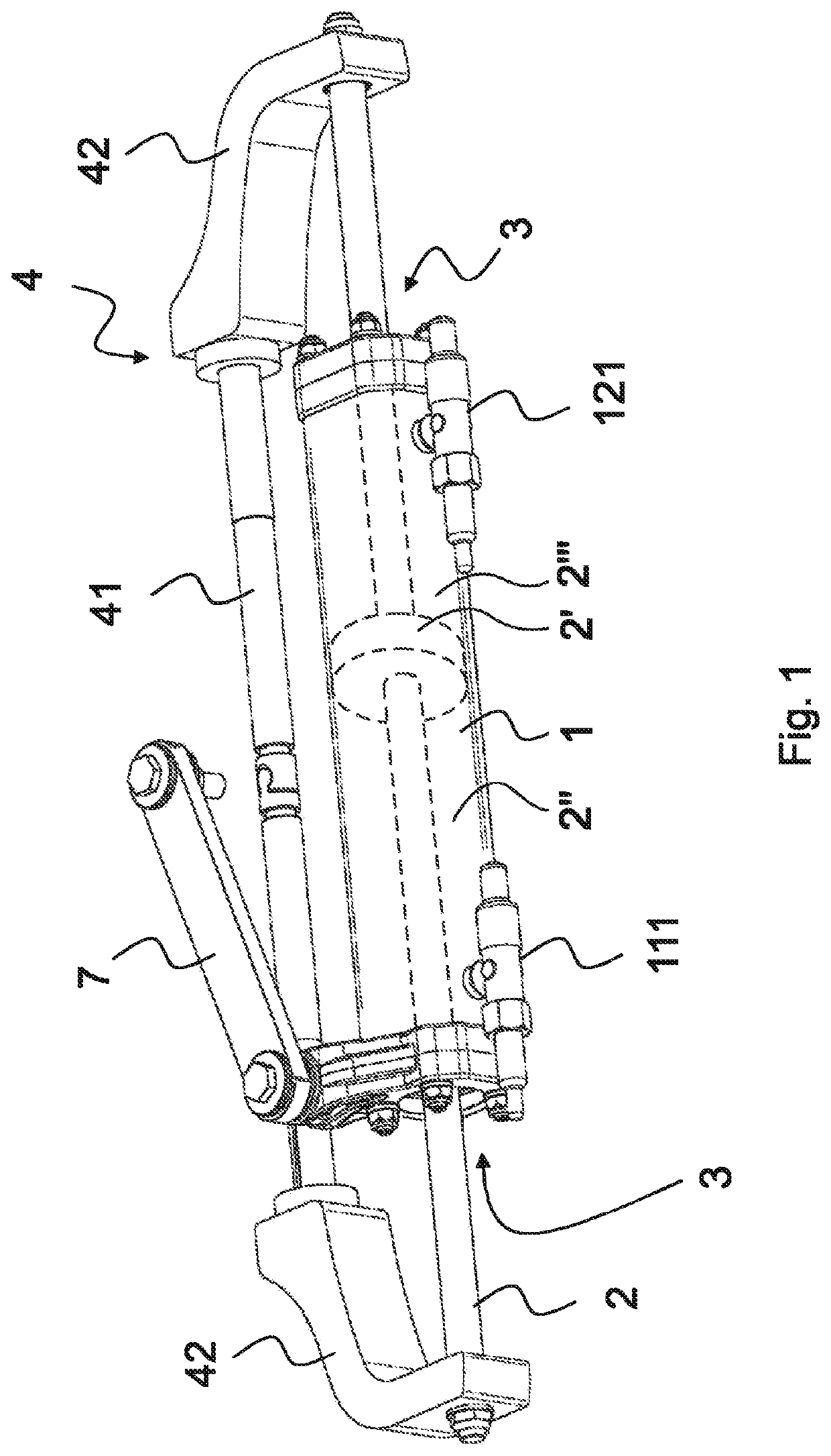
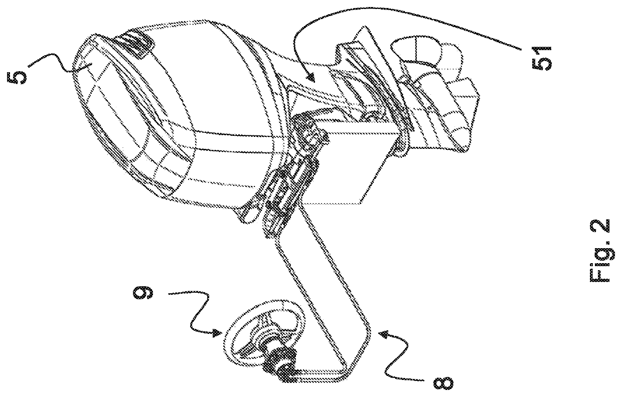
[0035]The figures in the present patent application show a preferred embodiment of the cylinder object of the present invention, but these figures should be considered for illustrative purposes only, to better understand concepts and advantages of the present invention.

[0036]In fact, these figures should not to be considered restrictive for the concept claimed in the Patent Application, the concept consisting of making an actuating cylinder with easily removable and replaceable fastening brackets.

[0037]Referring in particular to FIGS. 1 and 2, a hydraulic driving system for outboard marine engines is described hereinafter.

[0038]The system comprises a closed hydraulic circuit 8 with at least one pump 9 operated by steering means, such as a steering wheel, a rudder or the like.

[0039]The cylinder 1 is slidingly mounted on at least one rod 2 coaxial to the cylinder 1, which sealingly protrudes from at least one head of the actuating cylinder 1 and carries a separating piston 2′ that div...


PUM


Abstract

Double-acting hydraulic actuating cylinder, particularly for hydraulic steering devices of outboard marine engines. The cylinder is slidably mounted on at least one rod coaxial to the cylinder sealingly protruding from at least one head of the actuating cylinder and carrying a separating piston that divides the cylinder into two variable volume chambers, each one of such two chambers has an inlet / outlet for the hydraulic fluid, each connected to one of two inlets / outlets of the pump and a sealing head for the relative sliding between the cylinder and the rod, which sealing head is integral with the cylinder itself. The rod is provided to be connected to a fastening bracket to fasten the cylinder to the engine, in a not slidable manner and in such a way as to allow the relative rotation of the engine with respect to the transom along an axis parallel to the axis of the rod. The rod has at least one flattened surface to be grasped by a tool having at least one corresponding flat engagement surface for engaging said flattened surface.

Description

FIELD OF THE INVENTION[0001]The object of the present invention is a double effect, or double-acting, hydraulic actuating cylinder, particularly for hydraulic steering devices of outboard marine engines.BACKGROUND OF THE INVENTION[0002]Outboard engines generally comprise an end for the fastening to the transom of a watercraft on which the engine is mounted so as to rotate around a substantially vertical steering axis.[0003]The steering device comprises a closed hydraulic circuit with at least one pump actuated by steering means, such as a steering wheel, a rudder or the like, while the cylinder is slidably mounted on at least one rod coaxial thereto and sealingly protruding from at least one head of the actuating cylinder and carries a separating piston that divides the cylinder into two variable-volume chambers.[0004]Each of the two chambers has at least one inlet / outlet for the hydraulic fluid, each connected to one of two inlet / outlet of the pump, and a sealing head for the relat...

Claims


Application Information

Patent Timeline
Patent Type & Authority Patents(United States)
IPC IPC(8): B63H5/125B63H20/08B63H20/12F15B15/14B63H25/42B63H25/12
CPCF15B15/1457B63H20/12B63H25/42B63H25/12F15B2211/7054
Inventor GAI, MARCELLAPAGANI, ENRICO
Owner ULTRAFLEX
Learn More