Device for determining at least one parameter of a medium flowing in a line

a technology of at least one parameter and a line, applied in the direction of liquid/fluent solid measurement, volume metering, instruments, etc., can solve the problem of affecting the output signal of the measuring element, and achieve the effect of stabilizing the flow in the area and reducing the size of the dead water region

Inactive Publication Date: 2007-07-19
ROBERT BOSCH GMBH
View PDF9 Cites 3 Cited by
  • Summary
  • Abstract
  • Description
  • Claims
  • Application Information

AI Technical Summary

Benefits of technology

[0007] In an especially advantageous exemplary embodiment, provision is made for the wind shield to have openings which are made in the wind shield in the form of notches. Advantageously, the wind shield is formed by a comb-like structure of teeth arranged side by side in a row. When the device is used in a medium-carrying line, strong longitudinal eddies develop starting at the notches. The longitudinal eddies bring about an exchange of momentum between the slow flow of medium in the dead water region and the rapid flow of medium outside the dead water region, thereby advantageously reducing the size of the dead water region and stabilizing the flow in that area.

Problems solved by technology

The pressure variations in the measuring channel may cause considerable falsification of the output signal of the measuring element.

Method used


Image

  • Device for determining at least one parameter of a medium flowing in a line
  • Device for determining at least one parameter of a medium flowing in a line
  • Device for determining at least one parameter of a medium flowing in a line

Examples


Embodiment Construction

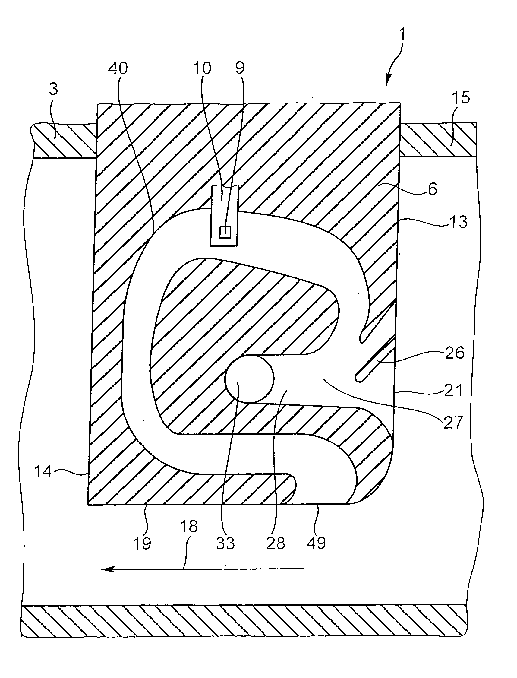
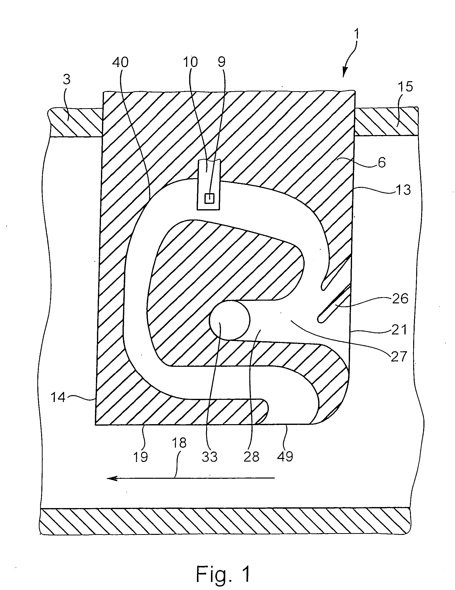
[0014]FIG. 1 shows a line 3 in which a medium flows in a main direction of flow. The main direction of flow is marked by a corresponding arrow 18 in FIG. 1 and runs from right to left therein. The main direction of flow is defined as being the direction in which the medium in the line flows through the line from the inlet of the line to the outlet of the line mainly in that direction, even though local eddy formations and local detached flow regions exhibit a local deviation in flow from the main direction of flow. The line may, for example, be an intake manifold of an internal combustion engine. The medium in question is, for example, air flowing in the intake manifold.

[0015] A device 1 according to the present invention is arranged in line 3 in such a manner that a part 6 of the device projects like a finger into line 3 and is exposed, with a predetermined orientation, to the medium flowing therein. When part 6 is being installed in line 3, it is ensured that part 6 has a predete...


PUM


Abstract

In a device for determining at least one parameter of a medium flowing in a main direction of flow in a line, which device has a part that can be inserted into the line with a predeterminable orientation in relation to the main direction of flow in such a manner that a partial stream of the medium flowing in the line passes into an entry region of a channel structure formed in the part, a measuring channel, provided with a measuring element for determining the at least one parameter, branching off from the entry region and the entry region having a separation zone which is separated from the measuring channel and has at least one separation aperture, which separation aperture opens into the line at a side wall of the part, which side wall extends substantially parallel to the main direction of flow, the part advantageously has at least one wind shield which is disposed downstream of the at least one separation aperture in the direction of the main direction of flow and which projects from the side wall provided with the separation aperture.

Description

FIELD OF THE INVENTION [0001] The invention relates to a device for determining at least one parameter of a medium flowing in a line BACKGROUND INFORMATION [0002] A device of that kind is known, for example, from German Patent No. 101 35 142 and is used, for example, in the intake system of an internal combustion engine in order to determine the air mass flow delivered to the internal combustion engine through a line. The known device has a channel structure with an inlet region from which a measuring channel, provided with the measuring element, branches off. The inlet region has a separation zone with at least one separation aperture situated at a side wall of the part of the device inserted into the line. The separation zone serves to remove liquid particles and / or solid particles from the channel structure, thus preventing them from entering the measuring channel which is provided with the measuring element, and contaminating the measuring element. [0003] The edges formed by the...

Claims


Application Information

Patent Timeline
Patent Type & Authority Applications(United States)
IPC IPC(8): G01M19/00G01F1/37G01P5/00G01M99/00G01F1/684G01F1/72G01F5/00G01F15/00G01F15/12
CPCG01F1/6842G01F15/12G01F5/00G01F1/72G01F15/00
Inventor KONZELMANN, UWEGMELIN, CHRISTOPH
Owner ROBERT BOSCH GMBH
Why Eureka
Try Eureka