Epicyclic reduction device for the rotational drive of blade sets of a reduction turbomachine

a technology of reducing device and blade set, which is applied in the direction of machines/engines, couplings, and gearing, can solve the problems of large noise, large amount of noise, and many drawbacks in the solution, and achieve the effect of increasing the tolerance of epicyclic gearing

Active Publication Date: 2019-12-03
SN DETUDE & DE CONSTR DE MOTEURS DAVIATION S N E C M A
View PDF22 Cites 0 Cited by
  • Summary
  • Abstract
  • Description
  • Claims
  • Application Information

AI Technical Summary

Benefits of technology

[0008]A main object of the present invention is thus to mitigate such drawbacks by proposing to increase the tolerance of the epicyclic gearing to misalignment when the turbine engine is subjected to deformation in operation, while maintaining the degrees of freedom that are essential for such operation. Another object of the invention is to provide a continuous transition of contact between the teeth while they are transmitting force so as to avoid transmission by jolts and associated impact phenomena.
[0010]The presence at one end of the sunwheel shaft of a constant velocity joint makes it possible to give the shaft a large amount of mechanical flexibility, both radially and angularly, so as to enable it to absorb the deformation to which the turbine engine is subjected in operation. This reinforces the ability of the elements of the epicyclic gear to withstand misalignment and the risks of wear.
[0015]This leads to a configuration that further improves the ability to obtain considerable radial flexibility for the shaft of the turbine rotor of the engine.

Problems solved by technology

By acting as bearing points seeking to bring misaligned shafts into alignment, the teeth are either subjected to premature wear, which is extremely deleterious to the lifetime of the gear as a whole, or else they require increased thicknesses of material of a kind that leads to highly penalizing constraints on integration when developing an on-board device of weight and size that must necessarily be minimized.
Nevertheless, that solution still presents numerous drawbacks.
In addition to such straight-tooth epicyclic gearing having power density that is rather low, it generates a large amount of noise, since force transmission is interrupted by jolts that occur on transition from one tooth to another, thereby generating metallic clicks.
Furthermore, the repeated mechanical impacts imposed on the teeth reduce their lifetime.
There therefore exists an unsatisfied need for an epicyclic gear device for a turbine engine with gearing in which the power density is significantly increased.

Method used


Image

  • Epicyclic reduction device for the rotational drive of blade sets of a reduction turbomachine
  • Epicyclic reduction device for the rotational drive of blade sets of a reduction turbomachine
  • Epicyclic reduction device for the rotational drive of blade sets of a reduction turbomachine

Examples


Embodiment Construction

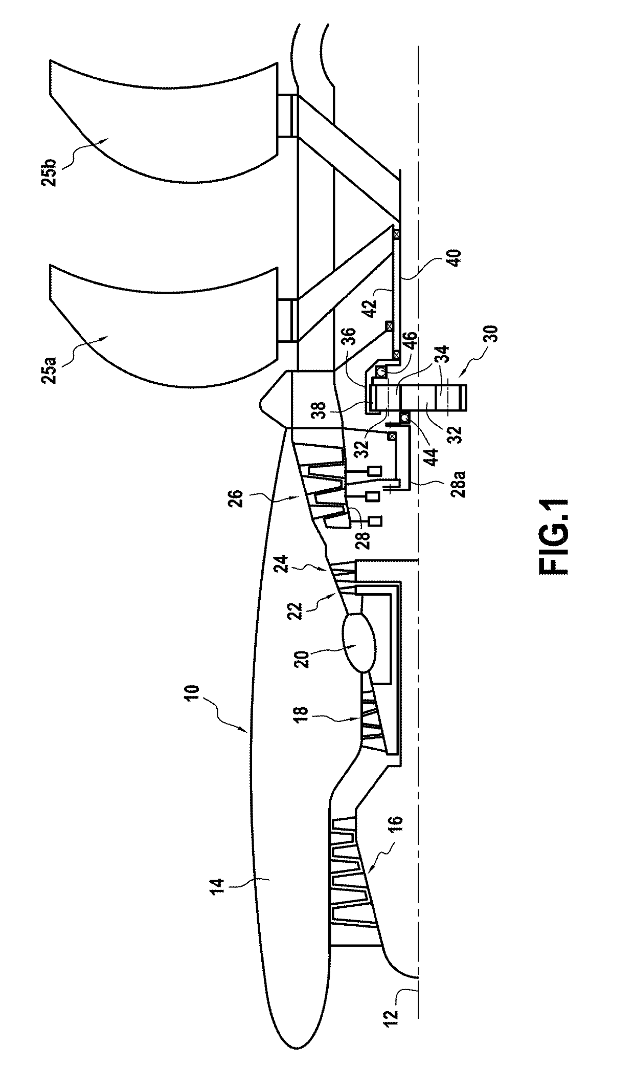
[0022]FIG. 1 is a highly diagrammatic view of an embodiment of an airplane turboprop of the type having two propellers (open rotor pusher) in which the epicyclic gear device of the invention can be incorporated. Such a turboprop is well known and is therefore not described in detail.

[0023]The turboprop 10 comprises in particular a longitudinal axis 12 and an annular nacelle 14 arranged coaxially around the longitudinal axis. From upstream to downstream, the turboprop 10 further comprises a low-pressure compressor 16, a high-pressure compressor 18, a combustion chamber 20, a low-pressure turbine 22, and an intermediate-pressure turbine 24.

[0024]Downstream from the intermediate-pressure turbine 24 there is a system of contrarotating propellers, namely an (upstream or front) first set 25a and a (downstream or rear) second set 25b of adjustable pitch blades driven in rotation by means of a low-pressure turbine 26 arranged downstream from the intermediate-pressure turbine 24. The low-pre...


PUM


Abstract

An epicyclic gear device for driving rotation of a first blade set of a turbine engine, the device: including a sunwheel centered on a longitudinal axis of the turbine engine and connected to a rotor of the engine in order to be driven in rotation; at least one planet meshing with the sunwheel; a planet carrier rotatably carrying the planet and connected to a first blade set in order to drive it in rotation; and a ring meshing with the planet; the sunwheel being connected to the rotor via a first constant velocity ball transmission joint.

Description

BACKGROUND OF THE INVENTION[0001]The present invention relates to the general field of turbine engines having gearing driven in rotation by means of a single turbine. It is thus equally applicable to airplane turboprops having one or two propellers comprising a single blade set or two unducted contrarotating blade sets, and to airplane turbojets having one or two fans comprising one blade set or two ducted contrarotating blade sets. The invention relates more particularly to an epicyclic gear device used between the shaft of the turbine rotor and the drive shaft(s) for driving rotation of the blade set(s) that is / are driven by the turbine.[0002]In known manner, an airplane turboprop with two propellers has two contrarotating unducted blade sets. In certain two-propeller turboprop architectures, the two blade sets are driven in rotation directly by a power turbine having two contrarotating rotors. In other architectures to which the present invention relates more particularly, the bl...

Claims


Application Information

Patent Timeline
Patent Type & Authority Patents(United States)
IPC IPC(8): F16H1/28F02C7/36F02K3/072F16D3/223
CPCF02C7/36F16D3/223F16H1/28F02K3/072Y02T50/671F05D2260/40311Y02T50/60
Inventor CURLIER, AUGUSTINAUSTRUY, JULIEN MICHEL PATRICK CHRISTIANBOUDEBIZA, TEWFIKCHARIER, GILLES ALAIN
Owner SN DETUDE & DE CONSTR DE MOTEURS DAVIATION S N E C M A
Why Eureka
Try Eureka