
Scan method, scan system and radiation scan controller

a scan controller and scan method technology, applied in the field of radiation, can solve the problems of over-the-actual required value of scanning, unnecessary radiation to relevant operators, and inability to adjust according to the varied situations of cargoes, so as to reduce the environmental dose level

Active Publication Date: 2019-12-03
NUCTECH CO LTD +1
View PDF11 Cites 1 Cited by
  • Summary
  • Abstract
  • Description
  • Claims
  • Application Information

AI Technical Summary

Benefits of technology

This approach ensures that higher dose rates or energy levels are applied where needed for better penetration and lower where not required, maintaining image quality while minimizing environmental radiation and shielding costs.

Problems solved by technology

However, since X-ray may cause radiation damage to human bodies and the environment, it is necessary to control the accelerator output dose rate in operation, or provide additional shielding protection or other measures, to meet the requirement of the environmental dose level.
However, in actual situation, the cargoes under inspection or the amounts of cargoes carried by containers / vehicles are usually different, so, the requirements of X-ray output dose rates and energy levels for a particular scan imaging system may vary greatly, which may cause a dose rate above an actually required value in scanning, additional shielding protection cost, or unnecessary radiation to relevant operators.
This scheme has gained successful applications in X-ray fast inspection system devices, however, it cannot be adjusted according to varied situations of cargoes, and thus has certain limitation.

Method used


Image

  • Scan method, scan system and radiation scan controller
  • Scan method, scan system and radiation scan controller
  • Scan method, scan system and radiation scan controller

Examples


Embodiment Construction

[0044]Below, the technical solution of this invention will be further described in detail with reference to the accompanying drawings and embodiments.

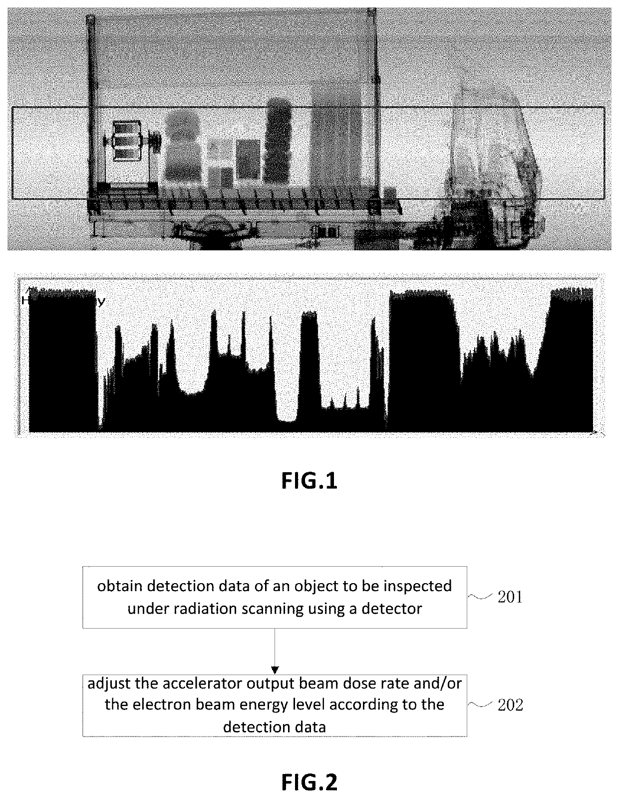
[0045]In a process of radiation detection, different data may be obtained by a detector from different regions of an object to be inspected due to its interior inhomogeneity. As shown in FIG. 1, an object to be inspected which is a vehicle is shown in the upper portion of FIG. 1, and detection data of corresponding locations is shown in the lower portion. It can be seen from FIG. 1, low energy radiation is obtained by the detector from locations on the vehicle having large mass thicknesses; from locations on the vehicle having smaller mass thicknesses or empty regions, high energy radiation is obtained by the detector. Based on the above reasons, a higher accelerator output beam dose rate or a higher electron output beam energy level may be adopted for locations having larger mass thicknesses, and a lower accelerator output beam dose r...


PUM

PropertyMeasurementUnit
energyaaaaaaaaaa
energy levelaaaaaaaaaa
imaging inspectionaaaaaaaaaa

Abstract

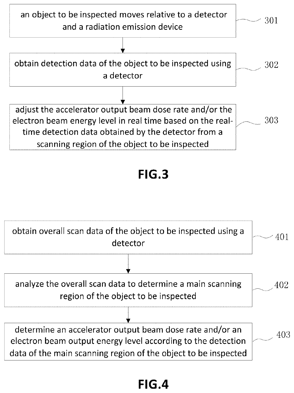
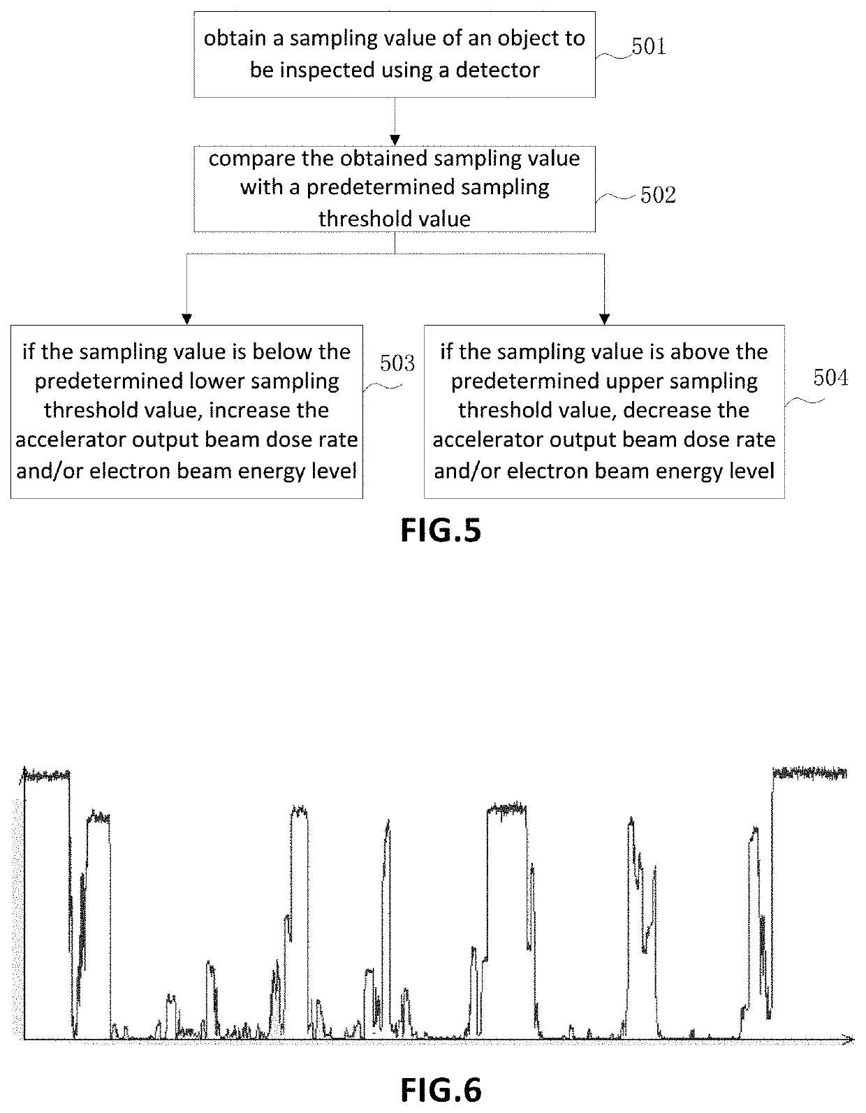
This invention provides a scan method, scan system and radiation scan controller, and relates to the field of radiation. Wherein, the scan method of this invention comprises: obtaining detection data of an object to be inspected under radiation scanning using a detector; adjusting an accelerator output beam dose rate and / or an output electron beam energy level of a radiation emission device according to the detection data. With this method, working conditions of the accelerator of the radiation emission device may be adjusted according to the detection data detected by the detector, so that for a region having a larger mass thickness, a higher output beam dose rate or a higher electron beam output energy level is adopted to guarantee satisfied imaging technical indexes, for a region having a smaller mass thickness, a lower output beam dose rate or a lower electron beam output energy level is adopted to reduce the environmental dose level while guaranteeing satisfied imaging technical indexes.

Description

FIELD OF THE INVENTION[0001]This invention relates to the field of radiation, particularly to a scan method, scan system and controller.BACKGROUND ART[0002]Currently, most of the X-ray light sources used in real-time containers / vehicle scanning and imaging systems are produced by linear electron accelerators having constant output dose rates. In general, imaging technical indexes of an inspection system, especially system penetrability, depends on the output dose rate of its accelerator, i.e., the higher the dose rate is, the better the penetrability is. However, since X-ray may cause radiation damage to human bodies and the environment, it is necessary to control the accelerator output dose rate in operation, or provide additional shielding protection or other measures, to meet the requirement of the environmental dose level.[0003]In order to meet the requirements for scanning under various different conditions, the accelerators' dose rates and energy levels of imaging systems are ...

Claims


Application Information

Patent Timeline
Patent Type & Authority Patents(United States)
IPC IPC(8): G01V5/00G01T1/29G01N23/04
CPCG01T1/29G01N23/04G01V5/0016G01N23/10G01V5/22G01N23/046
Inventor KANG, KEJUNLIU, YAOHONGZHAO, ZIRANJIA, WEIGU, JIANPINGTANG, CHUANXIANGCHEN, HUAIBIGAO, JIANJUNYIN, WEILIU, XIYING
Owner NUCTECH CO LTD
Learn More