

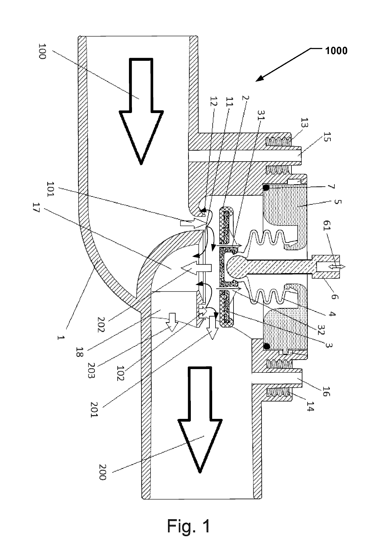
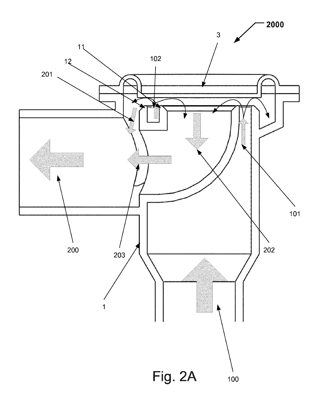
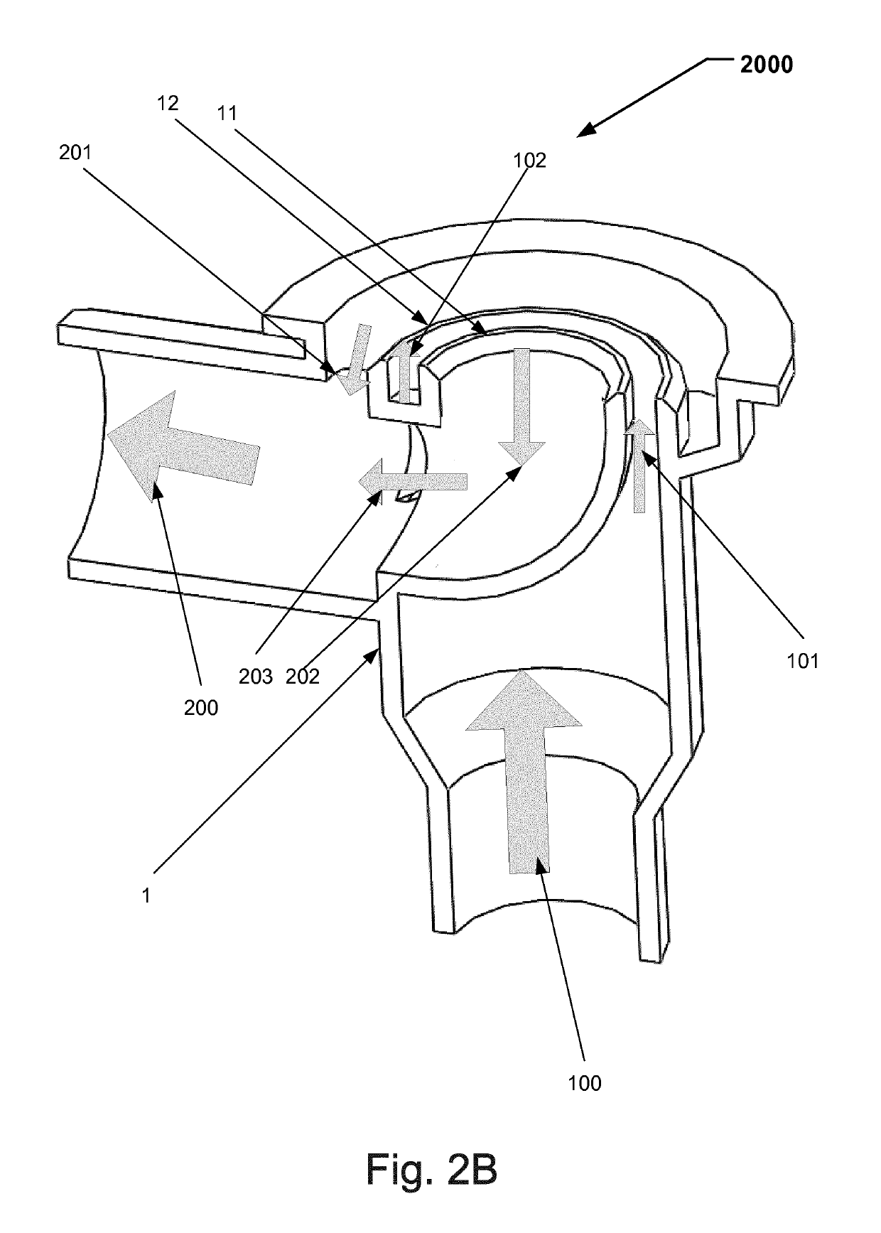
Valve for controlling a flow
a valve and flow technology, applied in the field of valves, can solve the problems of reducing pressure and losing energy, and achieve the effects of reducing area, improving stabilization properties, and small feedback on the inlet sid
- Summary
- Abstract
- Description
- Claims
- Application Information
AI Technical Summary
Benefits of technology
Problems solved by technology
Method used
Image

Examples
Embodiment Construction
[0023]Specific examples of the disclosure will now be described with reference to the accompanying drawings. This disclosure may, however, be embodied in many different forms and should not be construed as limited to the examples set forth herein; rather, these examples are provided so that this disclosure will be thorough and complete, and will fully convey the scope of the disclosure to those skilled in the art. The terminology used in the detailed description of the examples illustrated in the accompanying drawings is not intended to be limiting of the disclosure. In the drawings, like numbers refer to like elements.
[0024]The following description focuses on a valve to control a flow of a fluid through a flow channel. In particular the valve may be used in breathing machines or medical ventilators. An example of such a valve is an expiratory valve. However, it will be appreciated that the disclosure is not limited to this application but may be applied to many other mechanical va...
PUM
 Abstract
Description
Claims
Application Information