Transmission system

a transmission system and transmission system technology, applied in the direction of gearing, gearing elements, hoisting equipment, etc., can solve the problems of energy loss and component wear, the transmission of power by the drive member and the known drive sprocket is not efficient, and the known power transmission chain does not work efficiently on the drive sprocket, so as to maintain the alignment of the roller chain during use.

Pending Publication Date: 2021-09-30
NEW MOTION LABS LTD
View PDF5 Cites 0 Cited by
  • Summary
  • Abstract
  • Description
  • Claims
  • Application Information

AI Technical Summary

Benefits of technology

[0042]In such embodiments of the invention, because each tooth of the sprocket has a width which is the same as, or slightly less than the distance between inner surfaces of facing outer links, the tooth will fit between facing outer links with very little clearance between outside surfaces of the tooth and the inside surfaces of the facing outer links. The width of the tooth will also prevent the teeth from engaging between facing inner links, so the sprocket will be able to engage with the teeth between outer links only, and not between inner links. This help...

Problems solved by technology

The known drive members and known drive sprockets do not transmit power as efficiently as would be desired.
More specifically, the known drive members invariably make contact with the drive sprockets under significant loads, and in such situations, the drive members frequently tend to move relative to the teeth of the sprocket whilst maintain...

Method used


Image

  • Transmission system
  • Transmission system
  • Transmission system

Examples


Embodiment Construction

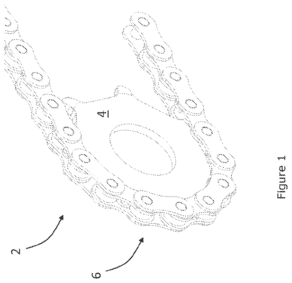
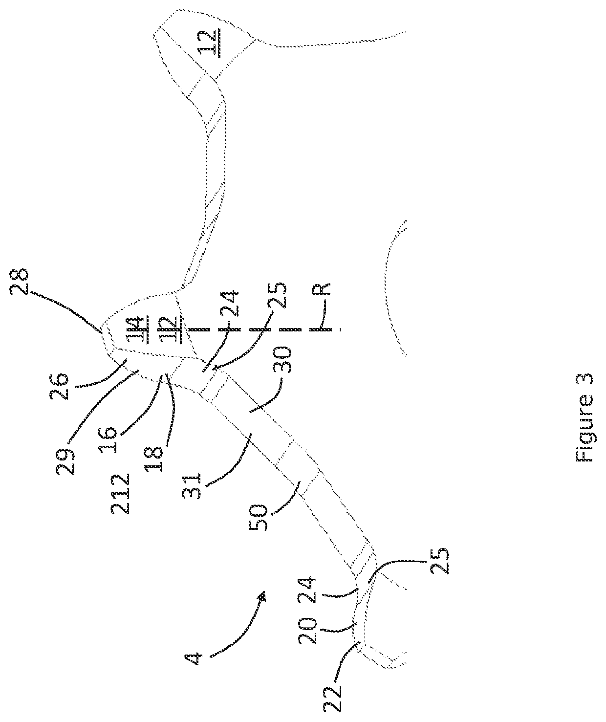
[0058]Referring initially to FIGS. 1 and 2 a transmission system according to an embodiment of the invention is designated generally by the reference numeral 2. The transmission system comprises a sprocket 4 and a drive member comprising a roller chain 6.

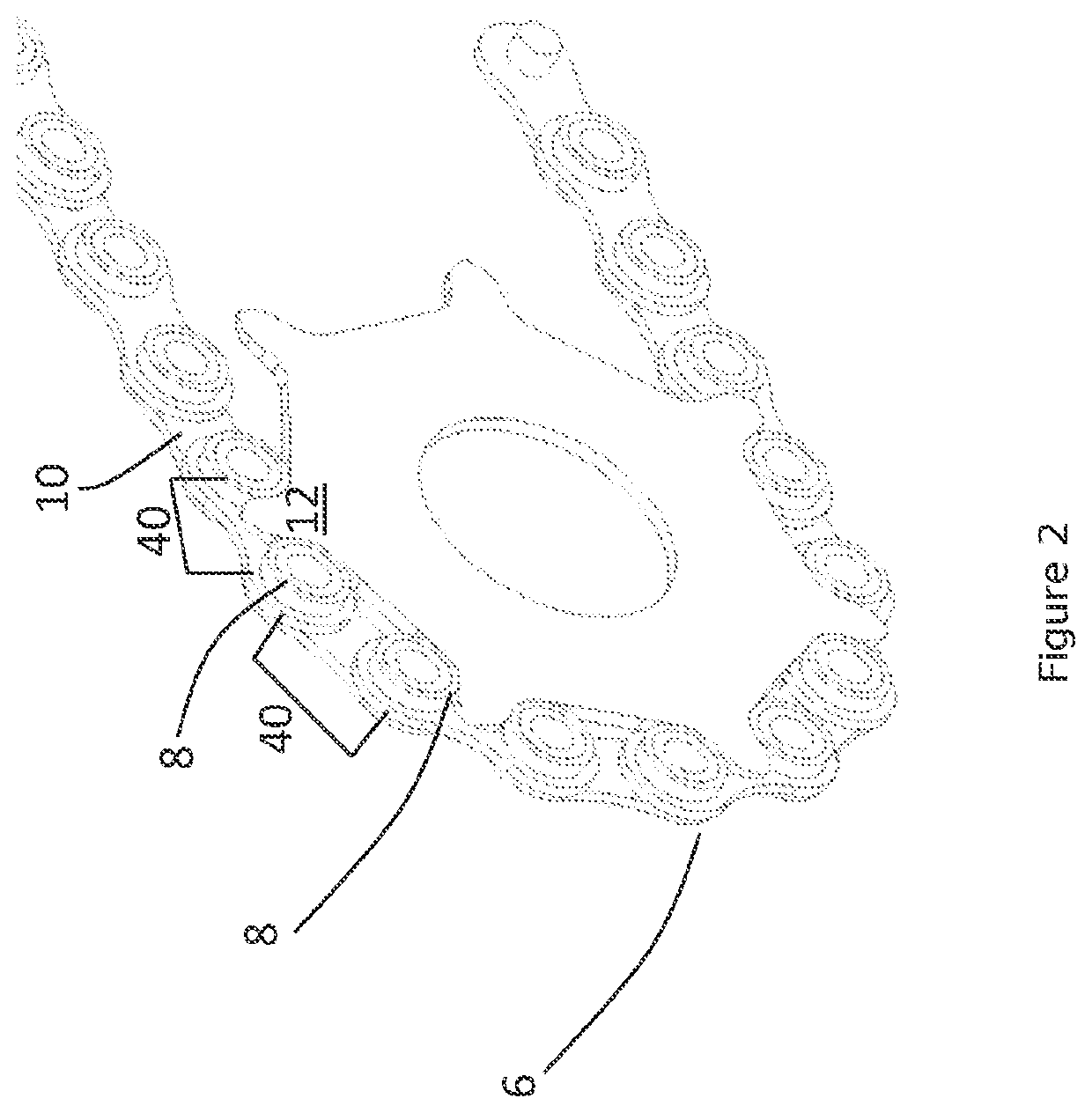
[0059]In this embodiment of the invention the roller chain 6 is a standard roller chain comprising a plurality of rollers 8 which extend transversely across the transmission member and are spaced apart along the length of the drive member to form the chain. The rollers are connected to one another by links 10 in a known manner. The roller chain 6 is able to articulate between adjacent rollers 8. An engagement pocket 40 is defined between adjacent rollers 8. Each engagement pocket 40 is adapted to engage with a tooth 12 as will be described in more detail below.

[0060]By means of the present invention, however, only every other engagement pocket 40 will engage with a tooth during use of the transmission system 2. The remaining every o...


PUM


Abstract

A transmission system can include a drive sprocket and a drive member adapted to mesh with the drive sprocket. The drive sprocket can include a plurality of teeth for meshing with the drive member to transmit rotary motion, and the drive member can include a plurality of engagement pockets adapted to engage the teeth of the drive sprocket.

Description

CROSS-REFERENCE TO RELATED APPLICATIONS[0001]This application is a continuation-in-part (CIP) application of U.S. patent application Ser. No. 16 / 629,918, filed Jan. 9, 2020, which is a national stage application of International Patent Application No. PCT / GB2018 / 000105, filed Jul. 10, 2018, which claims priority to Great Britain Application No. 1711342.4, filed Jul. 13, 2017, Great Britain Application No. 1715782.7, filed Sep. 28, 2017, and Great Britain Application No. 1717436.8, filed Oct. 24, 2017, the disclosures of all of which are incorporated herein by reference in their entirety, including any figures, tables, and drawings.BACKGROUND TO THE INVENTION[0002]This invention relates to a transmission system, and particularly, but not exclusively to a transmission system comprising a drive sprocket and a drive member, wherein the drive sprocket comprises a plurality of teeth. The invention also relates to a drive sprocket for use in a transmission system.[0003]Drive sprockets, or ...

Claims


Application Information

Patent Timeline
IPC IPC(8): F16H7/06F16H55/30F16G13/06
CPCF16H7/06F16G13/06F16H55/30
Inventor PALMER, JOSH DANIELLOBMEYER, LUCASFOWLER, MARCEL
Owner NEW MOTION LABS LTD
Why Eureka
Try Eureka