Device for measuring a measurement variable

a technology of a measurement variable and a measurement device, which is applied in the direction of measurement devices, geological measurements, instruments, etc., can solve the problems of limited connection of the resonance system, minimal measuring time, and inability to be used, so as to reduce the loss, improve the quality factor, and slow down the decay

Active Publication Date: 2018-11-01
CONTINENTAL TEVES AG & CO OHG
View PDF22 Cites 0 Cited by
  • Summary
  • Abstract
  • Description
  • Claims
  • Application Information

AI Technical Summary

Benefits of technology

[0043]An important property of oscillating circuits is their quality factor Q. This is a measure of the losses that arise by virtue of the ohmic resistance in the circuit, and of the decay of a free oscillation. The higher the quality factor, the lower the losses and the slower the decay.
[0044]FIG. 1 shows a family of curves that shows the effect of the quality factor on the benefit of supplementing the inductive system to form the oscillating circuit in relation to the stimulus—that is to say, the excitation by the excitation circuit. Plotted is the ratio of the current IL by virtue of the excited inductor to the current ISt of the stimulus. Without supplementing the inductive system to form the oscillating circuit, this ratio would always be equal to one, because there is no further current path. Since current IL corresponds to the useful current, because the magnetic flux is generated by it, whereas current ISt corresponds to the complexity, the plotted quotient signifies an evaluation factor for the benefit. Values greater than one correspond to a gain. This benefit has been plotted over the angular frequency ω normalized to the resonant-circuit frequency ω0. The family parameter is the quality factor; the value at ω0 in each curve corresponds to the value of the quality factor—that is to say, the curves represent the quality factor Q with the values 8; 6; 4; 2; 1; 1 / √2 (from top to bottom).

Problems solved by technology

The resonant system has limitations in connection with the layout of the inductive system, because only one oscillation per oscillator is possible.
Furthermore, the inductive system always exhibits frequency dependencies—that is to say, it can only be optimally designed for one frequency; the frequency range of the oscillator is always a compromise.
Depending upon the frequency, a minimal measuring-time is required for this, which under certain circumstances is simply not available.

Method used


Image

  • Device for measuring a measurement variable
  • Device for measuring a measurement variable
  • Device for measuring a measurement variable

Examples


Embodiment Construction

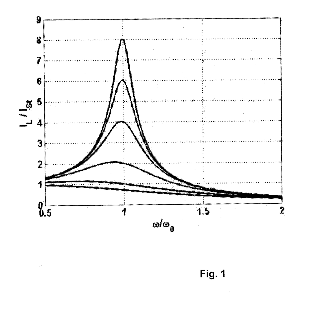
[0078]FIG. 1 has already been mentioned and elucidated in the text further above.

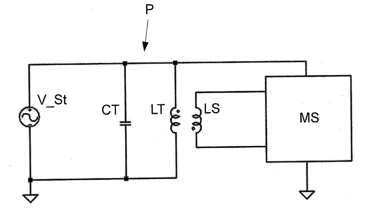
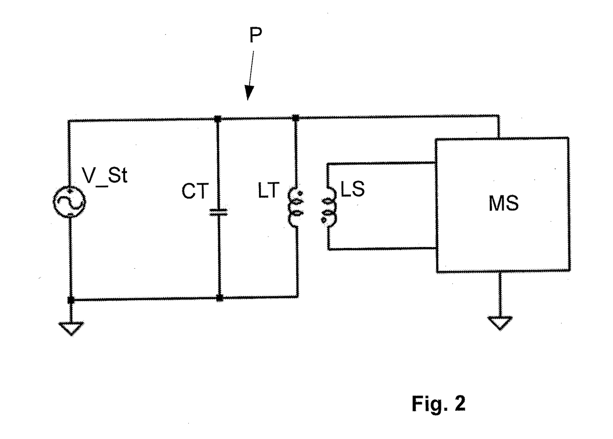
[0079]FIG. 2 shows an embodiment of a device according to the invention for measuring a measurable quantity, in which an inductive system is realized as a measuring transducer consisting of a first inductor LT and a measuring inductor LS.

[0080]The first inductor LT is connected up to a capacitor CT to form a parallel oscillating circuit P.

[0081]In the present case, the design of the device is such that the use of an amplifier can be dispensed with. In the present case it is also not necessary to insert an additional ohmic resistance for the purpose of reducing the quality factor Q of the parallel oscillating circuit P, because the parasitic resistance of the first inductor LT is sufficient to keep the quality factor Q within the permissible range.

[0082]For the purpose of exciting the parallel oscillating circuit P, an excitation circuit is provided in the form of a voltage source V_St which contains an ...


PUM


Abstract

A device for measuring a measurement variable, wherein a first inductance is replenished with a capacitance to form a parallel resonant circuit and the first inductance is coupled to a measurement inductance.

Description

CROSS REFERENCE TO RELATED APPLICATIONS[0001]This application is the U.S. National Phase Application of PCT International Application No. PCT / EP2016 / 068156, filed Jul. 29, 2016, which claims priority to German Patent Application No. 10 2015 215 330.4, filed Aug. 11, 2015, the contents of such applications being incorporated by reference herein.FIELD OF THE INVENTION[0002]The invention relates to a device for measuring a measurable quantity. In particular, said device may be an inductive sensor.BACKGROUND OF THE INVENTION[0003]Inductive sensors are based typically on an alteration of one or more characteristic values of a system of one or more inductive components by virtue of a measurable quantity. Inductive components of such a type may include, for instance, coil, winding or inductor.[0004]The following enter into consideration in particular as characteristic values:[0005]self-inductance L, also called inductance for short,[0006]loss resistance R, which is composed of an ohmic res...

Claims


Application Information

Patent Timeline
Patent Type & Authority Applications(United States)
IPC IPC(8): G01D5/243G01D5/20
CPCG01D5/243G01D5/2006G01D5/204G01V3/08
Inventor ACKER, HEINRICH
Owner CONTINENTAL TEVES AG & CO OHG
Why Eureka
Try Eureka