Electric current detection device and electric current detection method

a detection device and detection method technology, applied in the direction of measurement devices, electrical measurements, instruments, etc., can solve the problems of reducing detection accuracy, achieve high accuracy of magnetic field detection, compact device, and reduce induced electromotive force noise

Active Publication Date: 2019-12-10
HITACHI METALS LTD
View PDF3 Cites 0 Cited by
  • Summary
  • Abstract
  • Description
  • Claims
  • Application Information

AI Technical Summary

Benefits of technology

[0021]Based on the invention, it is possible to provide an electric current detection device and an electric current detection method by which a more compact device is possible and it is possible to reduce induced electromotive force noise by induced electromotive force between wires. Thus, by a compact configuration, it is possible to highly accurately detect a magnetic field generated by an electric current flowing through an electric current path and thereby possible to accurately detect the electric current flowing through the electric current path.

Problems solved by technology

Therefore, when the current value in the electric current path varies at a high frequency of about several tens kHz to several hundred kHz, induced electromotive force occurs between the wires of the magnetism detector elements and induced electromotive force noise is superimposed on the outputs of the magnetism detector elements, causing a decrease in detection accuracy.

Method used


Image

  • Electric current detection device and electric current detection method
  • Electric current detection device and electric current detection method
  • Electric current detection device and electric current detection method

Examples


first embodiment

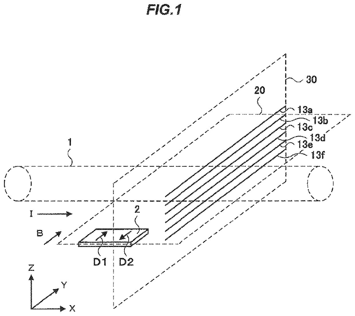
[0031]FIG. 1 is an explanatory diagram illustrating an electric current detection device in the first embodiment of the invention. When an electric current flows in the direction of the arrow I (in the X-direction) through an electric current path 1 indicated by a dotted line, a magnetic field in the direction of the arrow B (in the Y-direction) is generated at a position immediately below the electric current path 1. The magnetism detection portion 2 of the electric current detection device detects strength of the magnetic field generated by the electric current flowing through the electric current path 1.

[0032]The magnetism detection portion 2 has one or plural magnetism detector elements each of which has a magneto-sensitive axis in the direction of the arrow D1 (the positive Y-direction) or in the direction of the arrow D2 (the negative Y-direction).

[0033]Plural wires 13a, 13b, 13c, 13d, 13e and 13f connected to the magnetism detector elements and extending in a direction away f...

example 1

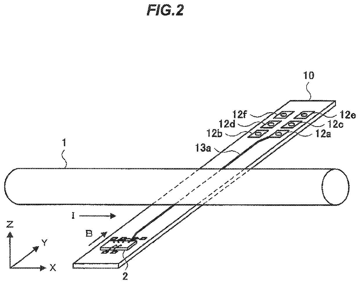
[0043]FIG. 2 is a perspective view showing an electric current detection device in Example 1 of the invention. Example 1 corresponds to the first embodiment and is configured that the magnetism detection portion 2 having the magnetism detector elements is mounted on the circuit board 10 having a multilayer structure composed of plural wiring layers on which the plural wires 13a, 13b, 13c, 13d, 13e and 13f are provided.

[0044]The circuit board 10 is arranged under the electric current path 1 through which an electric current flows in the direction of the arrow I (the X-direction). The magnetism detection portion 2 having the magnetism detector elements (described later) is mounted on the circuit board 10, and the magnetism detector elements of the magnetism detection portion 2 are arranged so that the directions of the magneto-sensitive axes lie in the first plane 20 shown in FIG. 1. The circuit hoard 10 also lies in the first plane 20 shown in FIG. 1.

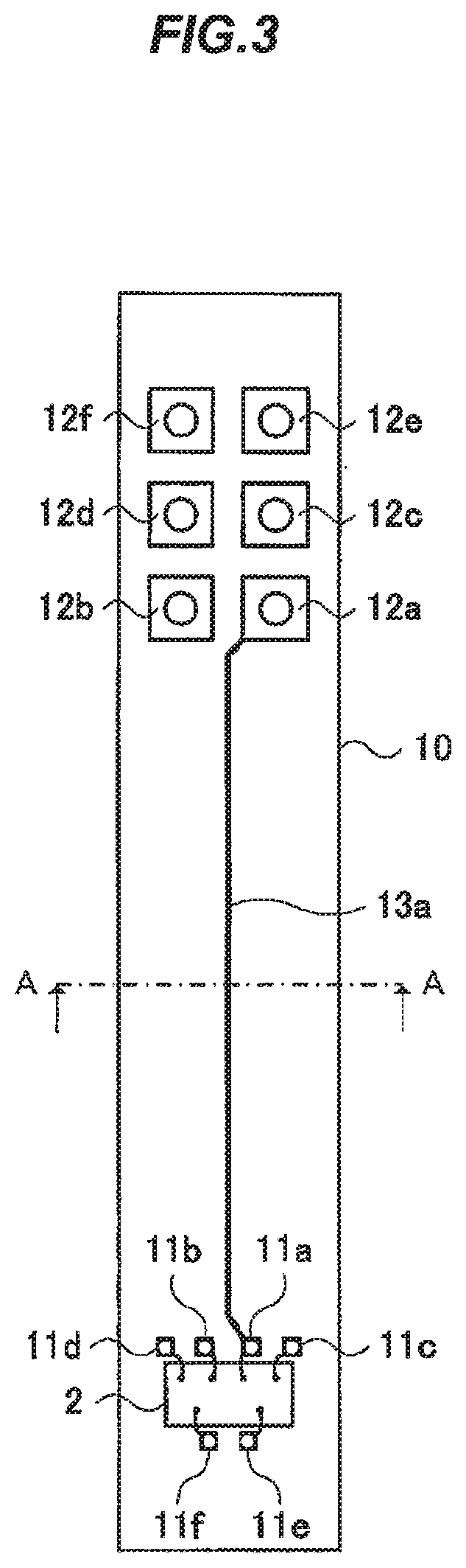
[0045]FIG. 3 is a top view showin...

second embodiment

[0060]FIG. 7 is an explanatory diagram illustrating an electric current detection device in the second embodiment of the invention. In the second embodiment, each of the wires 13a, 13b, 13c, 13d, 13e and 13f extends in a direction inclined by an angle θ in the X-direction relative to the Y-direction which is orthogonal to the current-carrying direction of the electric current path 1 (the X-direction). A second plane 30′ inclined by the angle θ in the X-direction relative to the second plane 30 which is orthogonal to the current-carrying direction of the electric current path 1 (the X-direction) is indicated by a dotted line in FIG. 7. The wires 13a, 13b, 13c, 13d, 13e and 13f are arranged on the same plane of the second plane 30′. The remaining configuration is the same as the first embodiment shown in FIG. 1.

[0061]Since the magnetism detector elements of the magnetism detection portion 2 are arranged so that the directions of the magneto-sensitive axes lie in the first plane 20, it...


PUM


Abstract

An electric current detection device includes magnetism detector elements for detecting a strength of a magnetic field generated by an electric current flowing through an electric current path, a detection circuit for detecting a magnitude of an electric current flowing through the electric current path based on an output of the magnetism detector elements, and plural wires that are connected to the magnetism detector elements and extend in a direction away from the electric current path. The magnetism detector elements are arranged such that a direction of a magneto-sensitive axis thereof lies on a first plane parallel to a current-carrying direction of the electric current path and parallel to an extending direction of the plurality of wires. The plural wires are arranged on a same plane of a second plane orthogonal to the first plane.

Description

CROSS-REFERENCE TO RELATED APPLICATIONS[0001]The present application is a U.S. National Phase of PCT / JP2014 / 077247 filed on Oct. 10, 2014. The disclosure of the PCT Application is hereby incorporated by reference into the present Application.TECHNICAL FIELD[0002]The present invention relates to an electric current detection device and an electric current detection method for detecting an electric current flowing through an electric current path by using magnetism detector elements.BACKGROUND ART[0003]In the field of, e.g., motor drive technology, etc., for hybrid cars or electric cars, etc., a relatively large current is used and there is thus a demand for electric current detection devices capable of non-contact measurement of a high current. Some of such electric current detection devices use a magnetism detector element(s) to detect strength of a magnetic field generated by an electric current to be measured, thereby detecting the magnitude of the electric current to be measured....

Claims


Application Information

Patent Timeline
Patent Type & Authority Patents(United States)
IPC IPC(8): G01R15/20
CPCG01R15/207
Inventor NOGUCHI, MASAKIFUTAKUCHI, NAOKIOKUYAMA, KEN
Owner HITACHI METALS LTD
Why Eureka
Try Eureka