
Mobile terminal

a mobile terminal and terminal technology, applied in the direction of instruments, electrical equipment casings/cabinets/drawers, instruments, etc., can solve the problems of large influence of air flow inside the terminal, inconvenience for users, and difficulty in efficiently preventing, so as to prevent noise generation and maintain waterproof performance.

Active Publication Date: 2019-12-10
LG ELECTRONICS INC
View PDF17 Cites 2 Cited by
  • Summary
  • Abstract
  • Description
  • Claims
  • Application Information

AI Technical Summary

Benefits of technology

[0009]Therefore, an aspect of the detailed description is to provide a structure of a mobile terminal capable of preventing generation of noise or abnormal noise generated in a receiver by guiding air flow inside generated according to pressure applied to the mobile terminal in a predetermined direction, while maintaining waterproof performance.
[0010]Another aspect of the detailed description is to provide a structure of a mobile terminal having a structure capable of minimizing an influence of air made on a receiver by lowering a speed of air moving along an air flow port.
[0012]In an embodiment of the present invention, a bent portion having a predetermined curvature to reduce a movement speed of air moving toward the receiver may be provided in a plurality of locations to further increase a movement distance of air.
[0024]In an embodiment of the present invention, the air moving along the inside of the air flow port moves toward the receiver in a state where the air is reduced in speed, so that the pressure applied to the receiver is reduced.
[0027]According to the mobile terminal having the structure described above, air moving according to the pressure applied to the rear cover is guided to the air vent hole, instead of the receiver, while moving along the air flow port, thereby minimizing noise or abnormal noise generated in the receiver.
[0028]In addition, the air flow port has a plurality of bent portions to reduce a flow rate of air, thereby reducing the influence of air made on the receiver.

Problems solved by technology

In recent years, as design of terminals has become simpler and its thickness has become thinner, there has been a problem that the influence of air flow inside terminals is large.
Particularly, in the case of a mobile terminal having a sealed structure for a waterproof specification, a noise or a abnormal noise of ticking is generated during a call due to flow of internal air generated due to an external force acting on the outside, causing inconvenience to users.
However, even when the space inside the terminal is reduced by attaching a tape or a film, air flow inside the terminal may be reduced but it is difficult to efficiently prevent flow of air flowing into the receiver, having a problem that it is difficult to prevent occurrence of abnormal noise, and since a tape or a film must be attached and manufactured according to a shape inside the terminal, it is disadvantageous in terms of cost.
In addition, deformation may occur over time.

Method used


Image

  • Mobile terminal
  • Mobile terminal
  • Mobile terminal

Examples


Embodiment Construction

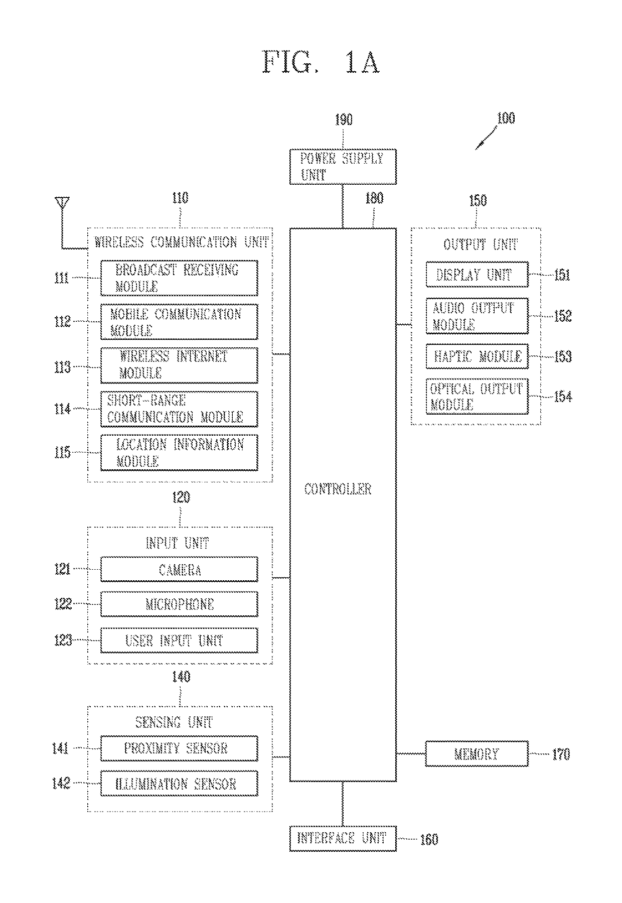
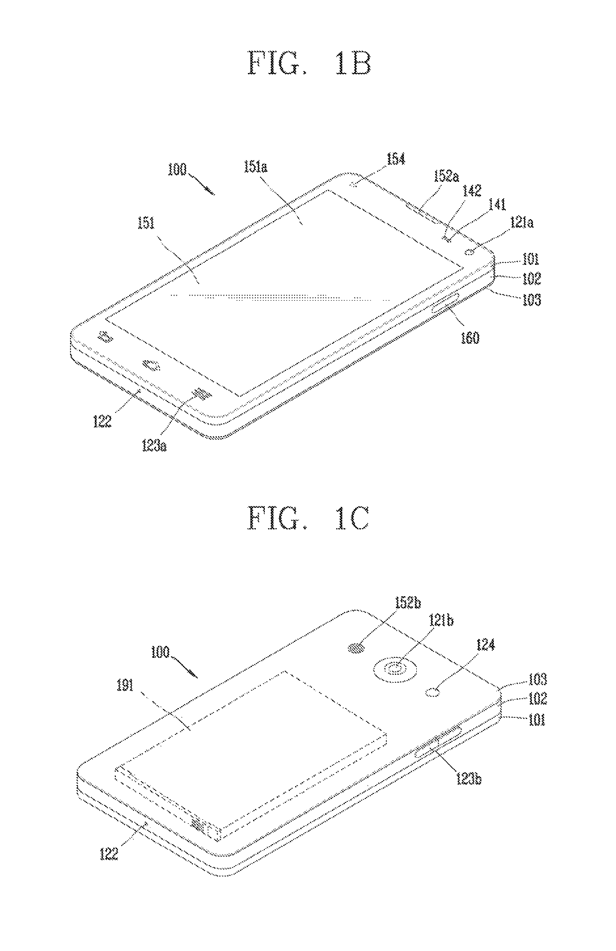
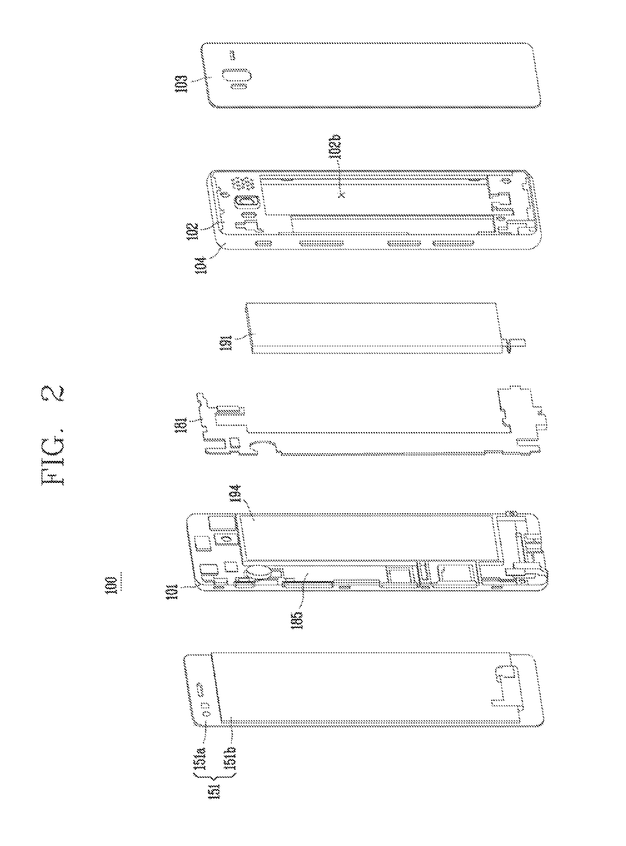
[0044]Description will now be given in detail according to exemplary embodiments disclosed herein, with reference to the accompanying drawings. For the sake of brief description with reference to the drawings, the same or equivalent components may be provided with the same or similar reference numbers, and description thereof will not be repeated. In general, a suffix such as “module” and “unit” may be used to refer to elements or components. Use of such a suffix herein is merely intended to facilitate description of the specification, and the suffix itself is not intended to give any special meaning or function. In describing the present disclosure, if a detailed explanation for a related known function or construction is considered to unnecessarily divert the gist of the present disclosure, such explanation has been omitted but would be understood by those skilled in the art. The accompanying drawings are used to help easily understand the technical idea of the present disclosure ...


PUM


Abstract

A mobile terminal includes a front case accommodating a display on a front surface and having a receiver for outputting a sound, a rear case coupled to one side of the front case, a rear cover covering a rear portion of the rear case to form an appearance and having an air vent hole allowing air to flow in and out to maintain predetermined pressure, and a circuit board installed been the front case and the rear case, wherein an air flow port is formed on an inner side surface of the rear cover and protrudes from the rear cover toward the rear portion of the case to guide movement of air formed by an external force acting on the rear cover.

Description

CROSS-REFERENCE TO RELATED APPLICATION[0001]Pursuant to 35 U.S.C. § 119(a), this application claims the benefit of earlier filing date and right of priority to Korean Application No. 10-2017-0178630, filed on Dec. 22, 2017, the contents of which is incorporated by reference herein in its entirety.BACKGROUND OF THE INVENTION1. Field of the Invention[0002]The present invention relates to a structure of a mobile terminal capable of guiding air moving inside a mobile terminal in a predetermined direction to limit the occurrence of abnormal noise during a call.2. Background of the Invention[0003]Terminals may be divided into mobile / portable terminals and stationary terminals according to mobility. Also, the mobile terminals may be classified into handheld types and vehicle mount types according to whether or not a user can directly carry.[0004]The terminal has various functions according to development of technologies. For example, an electronic device can be allowed to capture still ima...

Claims


Application Information

Patent Timeline
Patent Type & Authority Patents(United States)
IPC IPC(8): G06F1/20H04M1/02
CPCH04M1/0279H04M1/0277G06F1/203H04M1/0202H04M1/035H04M1/18H05K5/0213H04M1/026
Inventor CHA, YOUNGDOKIM, INSOOHAN, DONGWON
Owner LG ELECTRONICS INC
Learn More