
Sutureless valve prosthesis delivery device and methods of use thereof

a sutureless prosthesis and valve technology, applied in the field of sutureless prosthesis delivery devices and medical devices for implantation of prosthetic valve structures, can solve the problems of affecting the implantation efficiency of the prosthesis, the risk of damage to the vessel walls, and the difficulty of catheter-based delivery of the prosthesis, so as to achieve the effect of reducing damag

Active Publication Date: 2019-12-17
JC MEDICAL INC
View PDF52 Cites 4 Cited by
  • Summary
  • Abstract
  • Description
  • Claims
  • Application Information

AI Technical Summary

Benefits of technology

[0023]In one embodiment, the first or second sheath comprises a metal support structure and a protective layer. In another embodiment, the metal support structure is tubular in shape. In yet another embodiment, the metal support structure comprises a metal wire mesh. In still another embodiment, the metal support structure is fabricated from one or more thin-walled, flat-wire, metal helical coils. In one embodiment, the first or second sheath is comprised of a both a metal and a polymer which are fabricated together to form a long tube which can be bent to a bent configuration and which can maintain the bent configuration during a portion of or the entire delivery procedure.
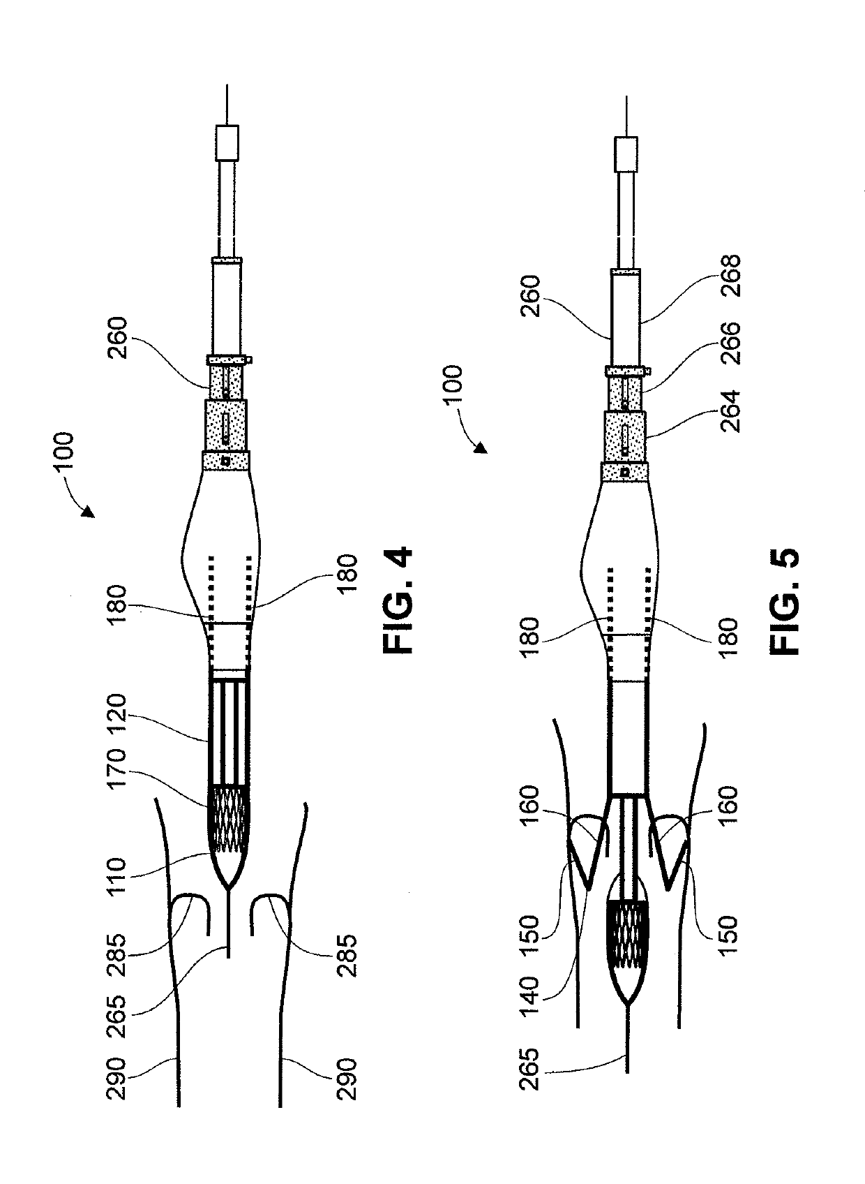
[0049]In one embodiment, the second sheath is comprised of a flexible material. In another embodiment, the second sheath comprises a metal support structure which is a braid of metal wires, a wire mesh and / or a wire coil. In another embodiment, the second sheath is able to bend sufficiently to conform to the curve of the vessel through which the delivery device is advanced. The wire support structure of the second sheath is fabricated such that the second sheath can be bent to a particular angle prior to introduction of the delivery device into a patient. Once bent, the second sheath maintains the bent angle throughout delivery of the prosthetic valve and retrieval of the delivery device. The bent angle can match or be compatible with delivery of the prosthetic valve to the native valve annulus, such that delivery does not result in damage to the native tissue near the point of valve replacement, or decreases damage relative to damage which might be caused if the second sheath were straight or bent with an angle less that about 5 degrees or less than about 3 degrees.

Problems solved by technology

Such open heart surgery is particularly invasive and involves a lengthy and difficult recovery period.
Nevertheless, challenges still remain in such catheter-based delivery of prosthetic valves.
Advancing a tubular delivery device through a vessel exerts stress against the vessel walls and is carries the risk of damaging the vessel walls.
For example, retrograde delivery of a valve through the femoral artery has been associated with aortofemoral artery injury / rupture, and carries a potential risk of stroke as the delivery involves crossing the aortic arch.
Other limitations of the related art will become apparent to those of skill in the art upon a reading of the specification and a study of the drawings.

Method used


Image

  • Sutureless valve prosthesis delivery device and methods of use thereof
  • Sutureless valve prosthesis delivery device and methods of use thereof
  • Sutureless valve prosthesis delivery device and methods of use thereof

Examples


Embodiment Construction

[0068]Various aspects now will be described more fully hereinafter. Such aspects may, however, be embodied in many different forms and should not be construed as limited to the embodiments set forth herein; rather, these embodiments are provided so that this disclosure will be thorough and complete, and will fully convey its scope to those skilled in the art.

I. Valve Claspers and Support Frame

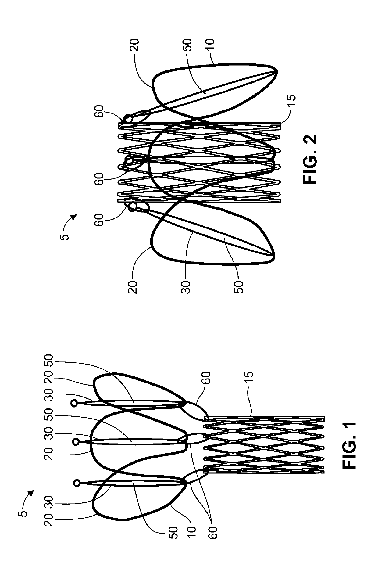
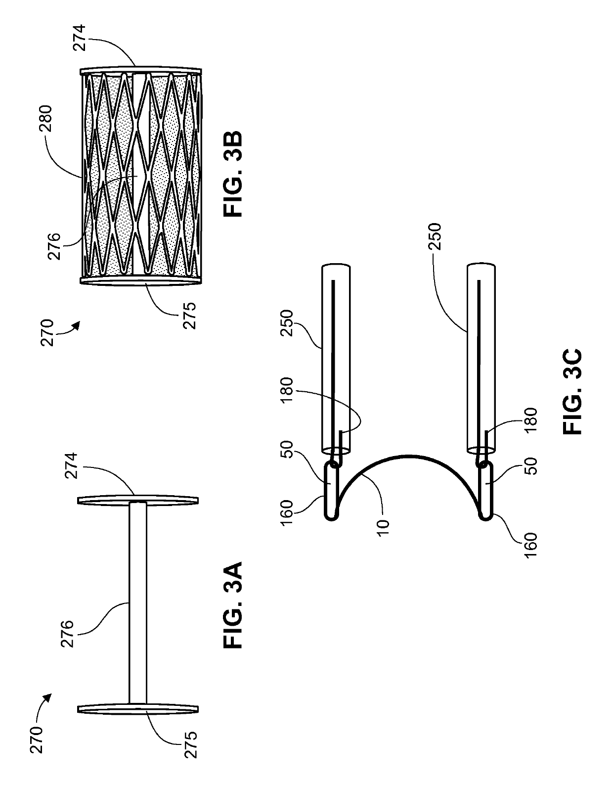
[0069]The implantation devices described herein comprise a delivery device which is configured to deliver a valve prosthesis to a defective heart valve in a patient. The valve prosthesis comprises the valve clasper which is moveably connected to a radially-expandable support frame comprising prosthetic valve leaflets. Valve claspers as described herein are movable relative to and along the longitudinal axis of the support frame. When the valve clasper is off-set from the support frame, e.g., when the u-shaped member of the valve clasper is in a position proximal or distal to the support frame a...


PUM


Abstract

Devices and methods for delivering a sutureless valve (5) to repair a defective native valve are described herein. The devices and methods are particularly useful in minimally invasive procedures.

Description

CROSS REFERENCE TO RELATED APPLICATIONS[0001]This application is a U.S. National Stage of International Patent Application No. PCT / US2014 / 029315, filed Mar. 14, 2014, which claims the benefit of priority to U.S. Provisional Application No. 61 / 784,973, filed Mar. 14, 2013, the disclosures of which are all incorporated herein by reference in their entirety.TECHNICAL FIELD[0002]The subject matter described herein relates to medical devices and methods for the implantation of a sutureless prosthetic valve structure using minimally invasive procedures.BACKGROUND[0003]Prosthetic heart valves are used to replace damaged or diseased heart valves. In vertebrate animals, the heart is a muscular organ with four pumping chambers: the left and right atria and the left and right ventricles, each provided with its own one-way valve. The natural heart valves are identified as the aortic, mitral (or bicuspid), tricuspid and pulmonary valves. Prosthetic heart valves can be used to replace any of thes...

Claims


Application Information

Patent Timeline
Patent Type & Authority Patents(United States)
IPC IPC(8): A61F2/06A61F2/24
CPCA61F2/2436A61F2/2427A61F2/2412A61F2/2418
Inventor ZHANG, JIWALSH, BRANDON G.
Owner JC MEDICAL INC
Learn More