Logging fracture toughness using drill cuttings

a drilling cutting and fracture toughness technology, applied in the field of geological formation assessment, can solve the problems of insufficient information for accurately determining the fracture toughness of subsurface formations, limited capability and accuracy, and high cost of traditional well assessment techniques, and achieve the effects of improving accuracy, reducing cost, and increasing tensile strength

Active Publication Date: 2019-12-17
SAUDI ARABIAN OIL CO
View PDF17 Cites 0 Cited by
  • Summary
  • Abstract
  • Description
  • Claims
  • Application Information

AI Technical Summary

Benefits of technology

[0008]Recognizing these and other shortcomings of traditional well assessment techniques and materials testing techniques, Applicants have developed novel systems and methods for determining fracture toughness of a subsurface geological formation using rock specimens fabricated from drill cuttings extracted during drilling of a wellbore into the formation. The techniques described can be employed, for example, over the course of a drilling operation to generate a log of fracture toughness across a depth interval of interest in the wellbore and the formation. With the combination of drill cuttings that are readily available, and the disclosed shaping and sizing of the specimens that can be formed from drill cuttings to accurately capture the properties of a KRS specimen, the proposed embodiments provide for accurately determining the fracture toughness of a subsurface formation including KRS, using readily available drill cuttings, and with little to no additional cost or delay in operating the well. Thus, the disclosed techniques can be employed, for example, to provide an accurate, real-time fracture toughness log for a well extending into a KRS formation, in a cost effective manner.
[0012]In some embodiments, the miniature SENB rock specimens are relatively small, having a volume in the range of about 10−8 m3 to about 10−10 m3. Such miniature SENB rock specimens can provide for isolation of the mechanical responses of different phases, especially the OM, from the clay particulates and minerals present in the specimen. In some embodiments, the miniature SENB rock specimens are of the millimeter (mm) scale, having a length in the range of about 1 mm to 100 mm. For example, each of the miniature SENB rock specimens may be a prismatic beam having a length (or “span”) of about 8 mm, a width of about 3 mm, and a thickness of about 2.3 mm, and having a notch having a depth of about of about 1 mm. The size and shape of such specimens bridges the gap between the coarse resolution of the large scale (or “core-scale”) samples used in some traditional rock mechanics assessment techniques, such as Brazilian tests, and the very fine resolution of the very small scale (or “micro-scale”) samples used in some traditional rock mechanics assessment techniques, such as nano-indentation test, while still complying with one or both of American Society for Testing and Materials (ASTM) standards and International Society for Rock Mechanics (ISRM) standards. Applicants have recognized that miniature SENB rock specimens of the described size and scale can isolate the contributions from individual components, especially the OM, to the emergent, systematic fracturing behavior of KRS. That is, miniature SENB rock specimens in the millimeter scale, which can be fabricated from drill cuttings, can overcome issues associated with the coarse resolution of the large scale samples and the very fine resolution of the very small scale samples, thereby providing an accurate and efficient technique for determining fracture toughness of a subsurface formation as a wellbore is being drilled into the subsurface formation. As described, the determination of fracture toughness of a subsurface formation can be used for planning and executing various operations relating to the subsurface formation, such as planning and executing as hydraulic fracturing operations in the subsurface formation, or planning and executing drilling operations, such as LCM management operations, for wells drilled into the subsurface formation.

Problems solved by technology

Applicants have recognized that traditional well assessment techniques can be costly, time consuming, and often have limited capability and accuracy.
Downhole logging operations, such as sonic logging operations, can be expensive and may not provide suitable information for accurately determining fracture toughness of subsurface formations.
Core sampling operations can be costly and time consuming.
Thus, the time and cost of a coring operation can include the time and cost of the coring operation itself, the time and cost to remove and re-run the drill string, as well as the added cost for operating the rig over the time period while drilling is suspended.
In addition to the direct cost associated with logging and coring operations, each of these operations has an increased risk associated with running additional tools into the wellbore.
For example, a tool can become lodged or otherwise lost downhole, which can lead to additional time and costs to retrieve the tool from the wellbore.
As a composite material consisting of compacted clay particles, silt-sized grains and organic matter (OM), KRS is highly complex both structurally and mechanically.
The OM, which is intertwined within the shale matrix, presents a particular challenge as it can be significantly more compliant than its surrounding minerals while at the same time having a significantly higher tensile strength.
Applicants have recognized that core-scale testing, such as Brazilian testing, fails in precisely capturing the effects of OM due to its coarse resolution.
Besides the limitations associated with collection and preparation of core sized specimens, it takes a greater amount of energy to open a fracture and, therefore, the individual effects of micro / nano scale organic matters cannot be isolated while measuring fracture toughness.
Applicants have also recognized that, although the very fine resolution nano-indention may capture the behavior of isolated components, it can miss collective properties of the overall composite system.
Thus, the scale of traditional rock mechanics assessment techniques can be too large or too small to accurately capture the properties of a KRS specimen.

Method used


Image

  • Logging fracture toughness using drill cuttings
  • Logging fracture toughness using drill cuttings
  • Logging fracture toughness using drill cuttings

Examples


Embodiment Construction

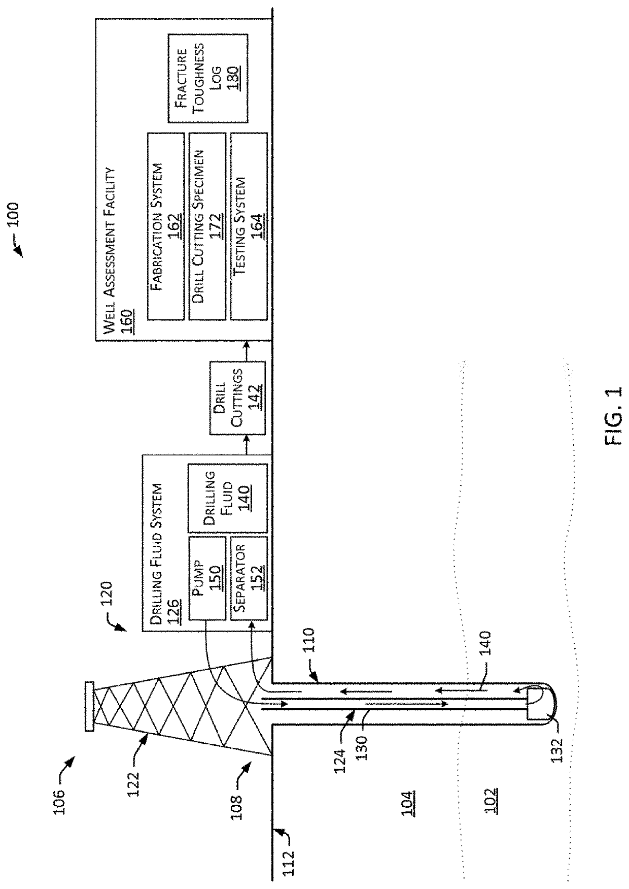
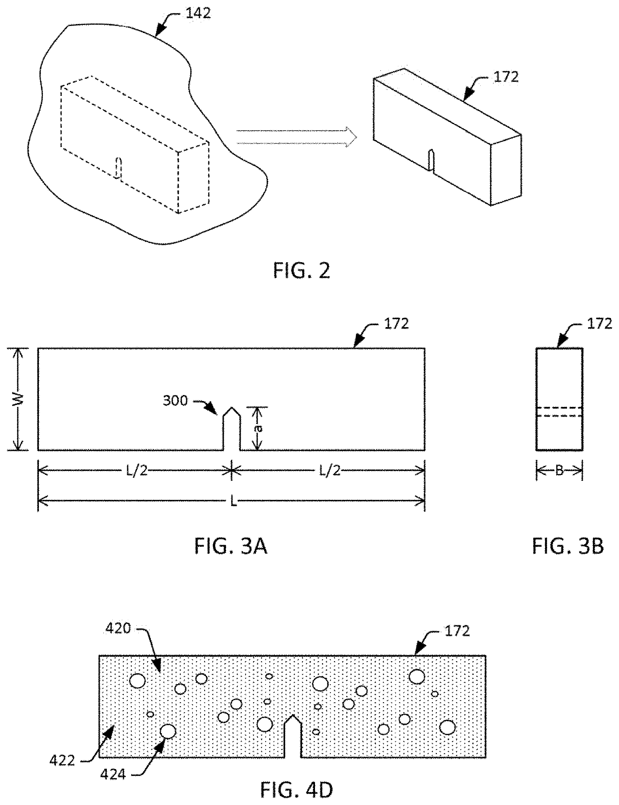
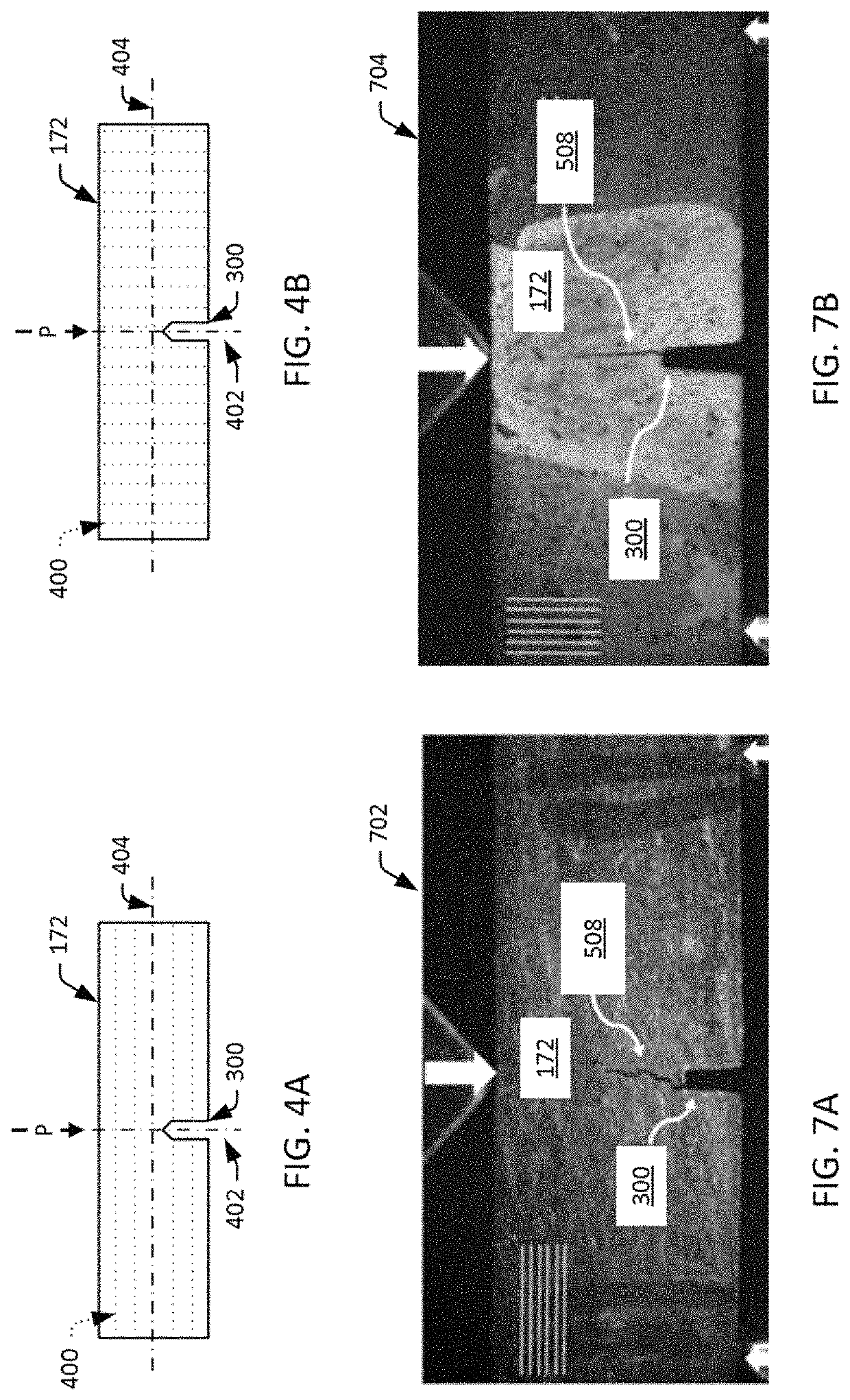
[0039]Described are embodiments of systems and methods for determining fracture toughness of a subsurface geological formation using rock specimens fabricated from drill cuttings extracted during drilling of a wellbore into the formation. The techniques described can be employed, for example, over the course of a drilling operation to generate a log of fracture toughness across a depth interval of interest in the wellbore and the formation. With the combination of drill cuttings that are readily available, and the disclosed shaping and sizing of the specimens that can be formed from drill cuttings to accurately capture the properties of a KRS specimen, the proposed embodiments provide for accurately determining the fracture toughness of a subsurface formation including KRS, using readily available drill cuttings, and with little to no additional cost or delay in operating the well. Thus, the disclosed techniques can be employed, for example, to provide an accurate, real-time fractur...


PUM


Abstract

Provided are systems and methods for determining fracture toughness of a subsurface geologic formation. Embodiments include collecting (from drilling fluid circulated into a wellbore during a drilling operation) a drill cutting generated by a drill bit cutting into a subsurface formation, preparing (from the drill cutting) a drill cutting specimen comprising a miniature single edge notch beam (SENB) having a specified length in the range of 1 millimeter (mm) to 100 mm, conducting a three-point bend testing of the drill cutting specimen to generate load-displacement measurements for the drill cutting specimen, and determining (based on the load-displacement measurements for the drill cutting specimen) a fracture toughness of the subsurface formation.

Description

RELATED CASES[0001]This patent application claims the benefit of U.S. Provisional Patent Application No. 62 / 514,326 filed Jun. 2, 2017 titled “Logging Fracture Toughness Using Drill Cuttings”, and U.S. Provisional Patent Application No. 62 / 515,840 filed Jun. 6, 2017 titled “Failure Behavior of Kerogen-Rich Shale (KRS) Composites at meso-scales”, each of which is incorporated herein by reference.FIELD[0002]Embodiments relate generally to assessing geological formations, and more particularly to determining fracture toughness of a subsurface geological formation using drill cuttings extracted during drilling of a wellbore into the formation.BACKGROUND[0003]A well typically includes a borehole (or “wellbore”) that is drilled into the earth to provide access to a geological formation below the earth's surface (or “subsurface formation”). A portion of a subsurface formation that contains (or is at least expected to contain) mineral deposits is often referred to as a “reservoir”. A reserv...

Claims


Application Information

Patent Timeline
Patent Type & Authority Patents(United States)
IPC IPC(8): E21B49/00E21B7/00E21B43/26
CPCE21B7/00E21B49/005E21B43/26
Inventor HAQUE, MOHAMMAD H.ABOUSLEIMAN, YOUNANE N.HULL, KATHERINE LEIGHHAN, YANHUI
Owner SAUDI ARABIAN OIL CO
Why Eureka
Try Eureka