Vibration damper arrangement

a damper and vibration technology, applied in the direction of springs/dampers, shock absorbers, functional characteristics, etc., can solve the problems of serial parts such as shock absorbers, complicated seals subject to increased wear, etc., and achieve precise control of compression stages, reduced cavitation risk, and higher damping values

Active Publication Date: 2019-12-17
HITACHI ASTEMO LTD
View PDF25 Cites 5 Cited by
  • Summary
  • Abstract
  • Description
  • Claims
  • Application Information

AI Technical Summary

Benefits of technology

[0008]The invention has the advantage that a setting of the asymmetry of the compression stage and the rebound stage of the vibration damper is possible by way of the provided connection of at least two check valves and at least two electro-rheological or magneto-rheological operating valves, without it being necessary to this end for the cross sections or diameter ratios of the piston rod and the piston to be taken into consideration. The asymmetry can thus additionally take place by way of the arrangement and control of the operating valves, with the result that the cross sections of the piston rod and the piston can be defined exclusively according to mechanical requirements. It is therefore also advantageously possible to design a homogeneous vibration damper for different asymmetries between the compression stage and the rebound stage solely by way of the connection and control of the operating valves, in order to realize the desired driving comfort without changing the mechanical properties of the vibration damper parts. Therefore, homogeneous damper embodiments can be used inexpensively as serial parts for different damping characteristics or different vehicle configurations.
[0009]The invention has the advantage, furthermore, that only two or three controllable operating valves and two simple check valves are necessary for the geometry-independent setting of the asymmetry of the rebound stage and the compression stage, in order for it to be possible to realize different driving experience stages even in the case of different vehicle configurations. Here, the invention has the advantage at the same time that this is even possible by way of a gas pressure accumulator with a low pilot pressure of at most 10 bar, as a result of which the risk of cavitation is reduced. As a result of the use of controllable magneto-rheological or electro-rheological operating valves, it is advantageous that the settings of different asymmetries between the compression stage and the rebound stage can take place without appreciable switching delays, with the result that very precise control of the compression stage and the rebound stage is possible during driving operation.
[0011]In the case of one special embodiment of the invention having electro-rheological operating valves which are integrated into the pressure medium cylinder, this has the advantage, in particular, that the operating valves can also be arranged outside the cylinder tubes coaxially between the pressure medium cylinder and the cylinder tubes as parallel or spiral gaps which are configured by way of at least two insulated cylinder tubes which are spaced apart and are at the same time the electrodes.
[0012]A further special embodiment of the invention having at least three controllable operating valves has the advantage that, as a result, the rebound stage can be damped by way of three operating valves, whereas the compression stage is damped by three operating valves with a reduced throughflow quantity, as a result of which the rebound stage is generally damped to a greater extent than the compression stage in the case of an identical control voltage, as a result of which an asymmetry is produced which largely corresponds to the driving experience stages which are provided in reality, with the result that only small asymmetry adaptations usually still have to take place by means of the control voltage. As a result, the control of higher damping values during rebound operation than compression operation is possible by way of lower control voltage changes, as a result of which the control accuracy can be increased. At the same time, the invention has the advantage that the geometry-independent asymmetry setting can be realized not only by way of electro-rheological operating valves, but rather also by way of magneto-rheological and rapid hydraulic operating valves.

Problems solved by technology

A pilot pressure which is as high as this has the disadvantage, however, that it requires a complicated seal which is subject to increased wear on account of the relatively high friction.
Since, in the case of dampers having an electro-rheological throttling valve, they are usually integrated into the cylinder tube, a separate damper arrangement would have to be produced for each piston rod cross section which is provided, which is disadvantageous, in particular, in the case of serial parts such as shock absorbers.

Method used


Image

  • Vibration damper arrangement
  • Vibration damper arrangement

Examples


Embodiment Construction

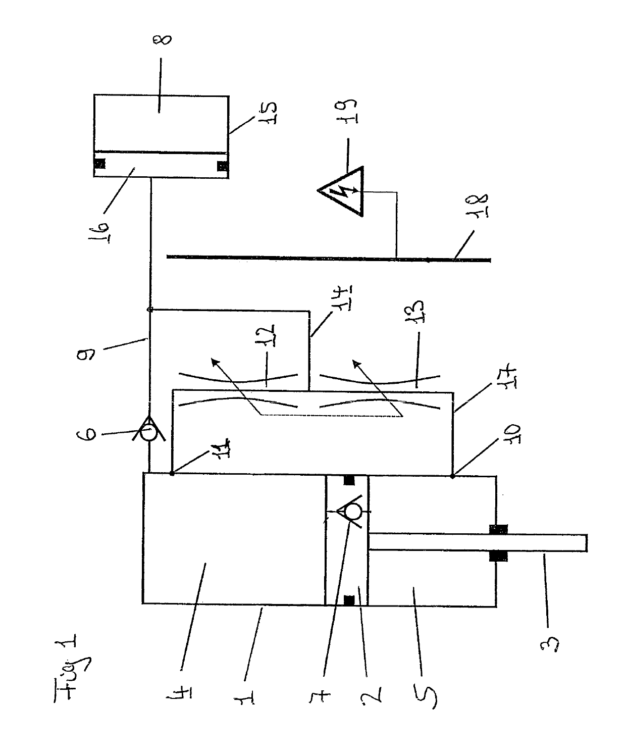
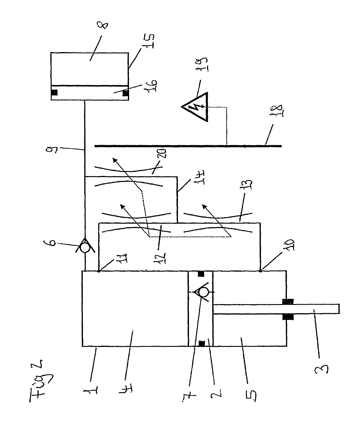
[0016]FIG. 1 shows a hydraulic operating and control circuit of an electro-rheological damper arrangement which comprises a pressure medium cylinder 1 and a longitudinally displaceable piston 2 which is provided with a piston rod 3, the piston 2 dividing the pressure medium cylinder 1 into a compression chamber 4 and a rebound chamber 5, through which the piston rod 3 runs. Here, the compression chamber 4 is connected via a first check valve 6 which opens or can open toward the latter to a gas pressure accumulator 8 via a first pressure medium line 9. At the same time, the compression chamber 4 is connected via a first overflow bore 11 to a first controllable electro-rheological operating valve 12 and, following this, a second controllable electro-rheological operating valve 13, and the outlet thereof is connected via a second overflow bore 10 to the rebound chamber 5. Here, a pressure medium branch 14 to the gas pressure accumulator 8 and the first check valve 6 is provided between...


PUM


Abstract

The invention relates to a vibration damper arrangement, in particular for damping compression and rebound forces on motor vehicles, which comprises a pressure medium cylinder (1), in which a piston (2) with a piston rod (3) is guided axially displaceably, which piston (2) divides the pressure medium cylinder (1) into a compression chamber (4) and a rebound chamber (5), a gas pressure accumulator (8) also being provided for volume compensation of the piston rod (3), which gas pressure accumulator (8) is connected to the compression chamber (4) by way of at least one first check valve (6) which can open toward the compression chamber (4), and a second check valve (7) which can open toward the rebound chamber (5) and, parallel thereto, at least one first controllable operating valve (12) being provided between the compression chamber (4) and the rebound chamber (5).

Description

CROSS-REFERENCE TO RELATED APPLICATIONS[0001]This application claims priority to PCT / EP2016 / 000884, filed 30 May 2016, which claims benefit to German Application No. 102015006721.4 filed on 19 May 2015.BACKGROUND OF THE INVENTIONField of the Invention[0002]The invention relates to a vibration damper arrangement, in particular for damping compression and rebound movements preferably on motor vehicles, in accordance with the preamble of patent claim 1.Description of Related Art[0003]Vibration damper arrangements of this type are frequently used as shock absorbers in motor vehicles. Here, the shock absorbers consist substantially of a cylinder which is filled with liquid and in which a piston which is fastened to a piston rod is guided axially. Here, the piston divides the pressure medium cylinder into a compression chamber and into a rebound chamber, through which the piston rod runs. In the case of an axial movement of the piston rod with respect to the cylinder, the liquid usually f...

Claims


Application Information

Patent Timeline
Patent Type & Authority Patents(United States)
IPC IPC(8): F16F9/46F16F9/53B60G13/08F16F9/19B60G17/016F16F9/06
CPCF16F9/065F16F9/532B60G17/016B60G13/08F16F9/064F16F9/19F16F9/46F16F2228/066F16F2222/06F16F2224/043B60G2500/10B60G2206/41
Inventor FUNKE, JOACHIM
Owner HITACHI ASTEMO LTD
Why Eureka
Try Eureka