Optical system of a microlithographic projection exposure apparatus

a microlithographic and exposure apparatus technology, applied in the direction of polarising elements, printing machines, instruments, etc., can solve the problems of reducing the so-called ips value, unable to compensate for the retardation of the system, and the ips value can prove complex

Active Publication Date: 2015-01-29
CARL ZEISS SMT GMBH
View PDF2 Cites 2 Cited by
  • Summary
  • Abstract
  • Description
  • Claims
  • Application Information

AI Technical Summary

Benefits of technology

[0011]It is an object of the present invention to provide an optical system of a microlithographic projection exposure apparatus which makes possible, in a flexible manner or for different polarization distributions, an effective compensation of the above-described system retardation with comparatively little complexity.
[0016]a retarder arrangement, which is arranged upstream of the polarization-influencing optical arrangement in the light propagation direction and at least partly compensates for a disturbance of the polarization distribution that is present elsewhere in the projection exposure apparatus;
[0020]The positioning of the retarder arrangement according to the invention upstream of the polarization-influencing optical arrangement in this case has the advantage, in particular, that the use of a multiplicity of different components of the retarder arrangement for the different polarization states produced by the polarization-influencing optical arrangement is dispensable. This is because the different polarization states or different polarization rotation angles are produced only after passing through the retarder arrangement according to the invention, in which case, as described above, the elliptically polarized component produced by the retarder arrangement and required for the compensation of the system retardation is concomitantly rotated by the polarization-influencing optical arrangement.
[0031]In accordance with a further embodiment, the retarder arrangement has a photoelastic modulator as a switchable element, in order to make it possible to set the absolute value of the retardation provided.

Problems solved by technology

During the operation of a projection exposure apparatus, the problem occurs, inter alia, that on account of birefringence occurring in the material of the optical components such as e.g. lens elements (e.g. intrinsic birefringence in calcium fluoride), stress birefringence (owing to mounts or material stresses in the production process) or layer birefringence, an undesirable system retardation occurs which results in a reduction of the so-called IPS value (i.e. the “Intensity in Preferred State”).
Compensation of this system retardation for the purpose of increasing the IPS value can prove to be complex in this case in so far as the retardation has a vectorial character in so far as light rays having mutually different polarization states effectively experience different retardations, the system retardation moreover having a comparatively pronounced field and pupil dependence.

Method used


Image

  • Optical system of a microlithographic projection exposure apparatus
  • Optical system of a microlithographic projection exposure apparatus
  • Optical system of a microlithographic projection exposure apparatus

Examples


Embodiment Construction

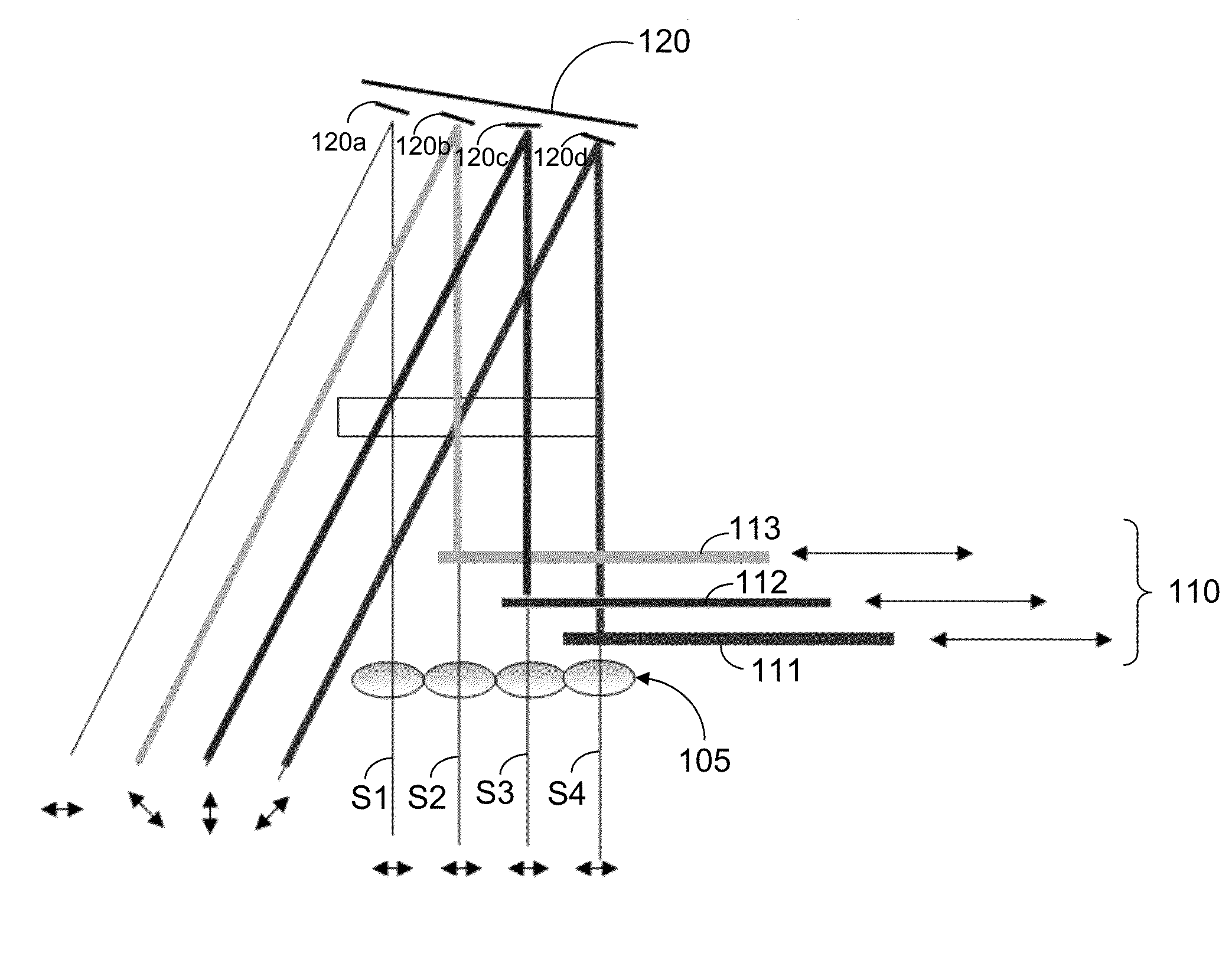
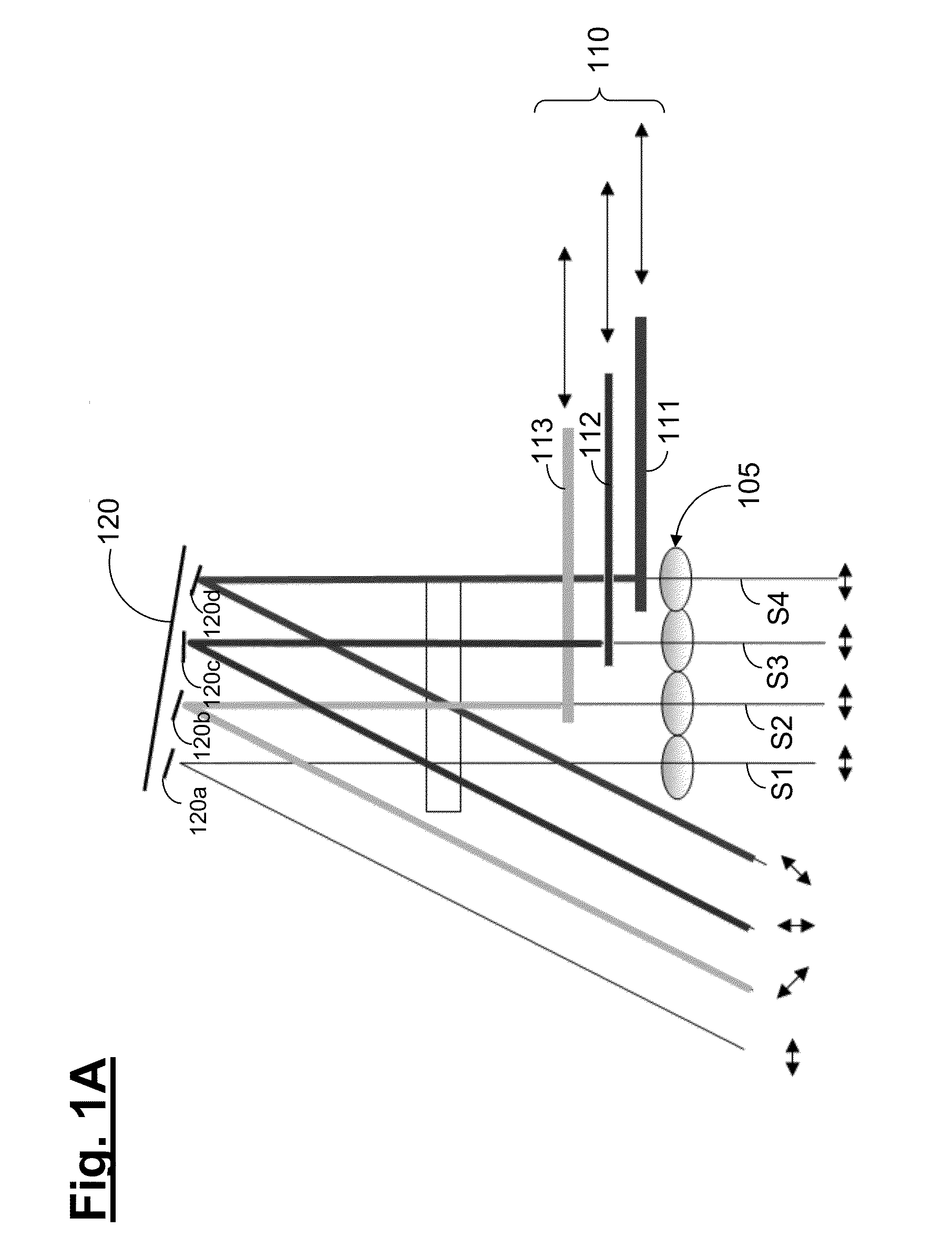
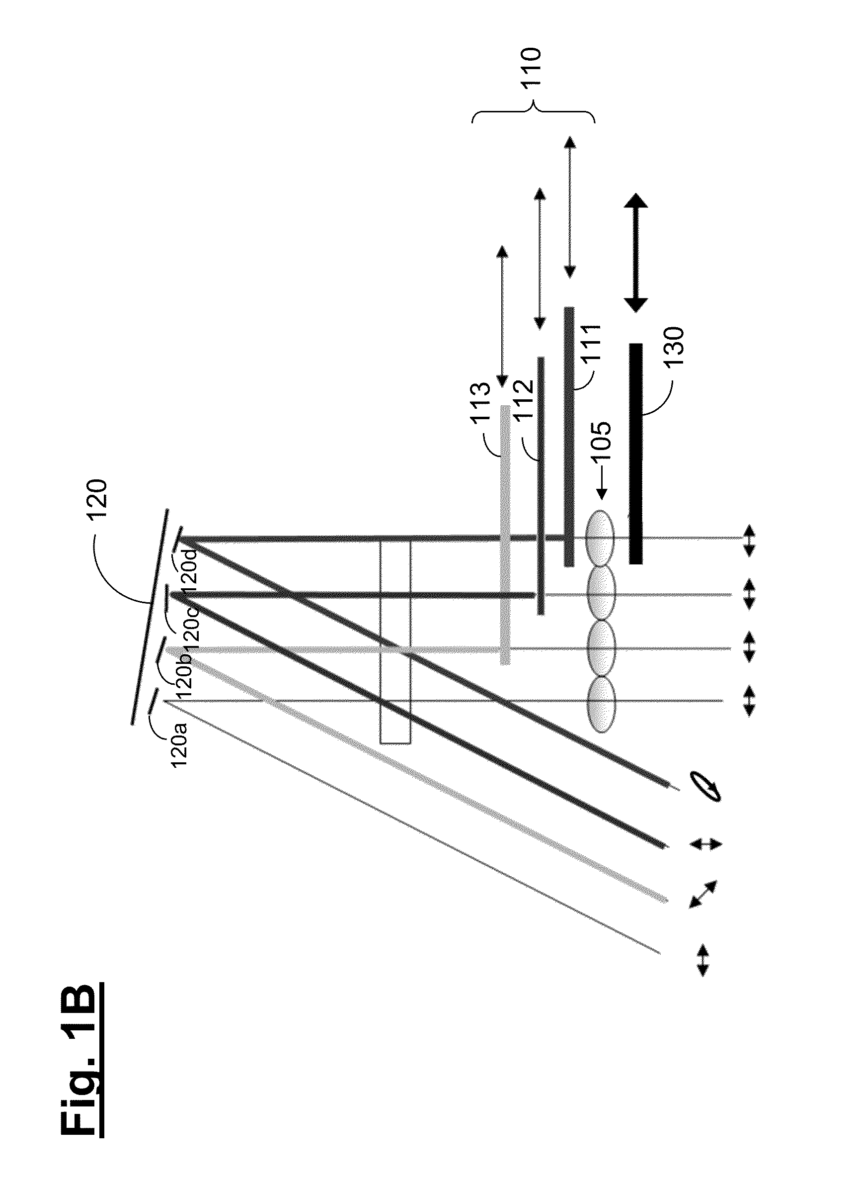
[0038]Firstly, with reference to FIG. 11, a basic construction of a microlithographic projection exposure apparatus comprising an optical system according to the invention is explained below. The projection exposure apparatus has an illumination device 10 and a projection lens 20. The illumination device 10 serves for illuminating a structure-bearing mask (reticle) 30 with light from a light source unit 1, which comprises, for example, an ArF excimer laser for an operating wavelength of 193 nm and a beam shaping optical unit, which generates a parallel light beam. Generally, the illumination device 10 and the projection lens 20 are preferably designed for an operating wavelength of less than 400 nm, in particular less than 250 nm, more particularly less than 200 nm.

[0039]According to the invention, part of the illumination device 10 is in particular, a mirror arrangement 120 having a multiplicity of mirror elements that can be set independently of one another. A polarization-influen...


PUM

PropertyMeasurementUnit
polarization rotation anglesaaaaaaaaaa
operating wavelengthaaaaaaaaaa

Abstract

An optical system of a microlithographic projection exposure apparatus comprises at least one mirror arrangement, having a plurality of mirror elements which are adjustable independently of one another for varying an angular distribution of the light reflected by the mirror arrangement, a polarization-influencing optical arrangement, by which, for a light beam passing through during the operation of the projection exposure apparatus, different polarization states can be set via the light beam cross section, and a retarder arrangement, which is arranged upstream of the polarization-influencing optical arrangement in the light propagation direction and at least partly compensates for a disturbance of the polarization distribution that is present elsewhere in the projection exposure apparatus, wherein the polarization-influencing optical arrangement has optical components which are adjustable in their relative position with respect to one another, wherein different output polarization distributions can be produced by this adjustment in conjunction with the mirror arrangement.

Description

CROSS REFERENCE TO RELATED APPLICATIONS[0001]The present application is a continuation of, and claims benefit under 35 USC 120 to, international application PCT / EP2013 / 054202, filed Mar. 1, 2013, which claims benefit under 35 USC 119 of German Application No. 10 2012 205 045.0, filed Mar. 29, 2012. International application PCT / EP2013 / 054202 also claims priority under 35 USC 119(e) to U.S. Provisional Application No. 61 / 617,130, filed Mar. 29, 2012. The content of each of these applications is hereby incorporated by reference.BACKGROUND OF THE INVENTION[0002]1. Field of the Invention[0003]The invention relates to an optical system of a microlithographic projection exposure apparatus. In particular, the invention relates to an optical system of a microlithographic projection exposure apparatus which makes possible, for different polarization distributions, an effective compensation of an undesirable system retardation with comparatively little complexity.[0004]2. Prior Art[0005]Micro...

Claims


Application Information

Patent Timeline
Patent Type & Authority Applications(United States)
IPC IPC(8): G03F7/20G02B5/30
CPCG02B5/3083G03F7/70191G03F7/70116G03F7/70566G03F7/70966
Inventor SCHLESENER, FRANKSAENGER, INGO
Owner CARL ZEISS SMT GMBH
Why Eureka
Try Eureka