Communication sheet structure

a communication sheet and structure technology, applied in the field of communication sheets, can solve the problems of information leakage, unauthorized access, and obstruction of walking or an appearance, and achieve the effect of convenient setting on the desk

Active Publication Date: 2013-10-29
TEIJIN FRONTIER CO LTD
View PDF19 Cites 2 Cited by
  • Summary
  • Abstract
  • Description
  • Claims
  • Application Information

AI Technical Summary

Benefits of technology

[0025]Use of the communication sheet structure of the present invention enables carrying of the communication sheet structure in a wound roll form, which facilitates setting on a desk for an office, and setting in the field of inventory control or physical distribution management. Further, setting of a single sheet structure over the entire wall surface or over the entire floor surface becomes possible, which is useful for development of home security.

Problems solved by technology

In such circumstances, when a LAN cable is used, the cable is routed in a house or an office, causing an obstruction to walking or an appearance problem.
Whereas, when wireless LAN is used, communication is performed using radiation of electric waves, which causes security problems such as information leakage and an unauthorized access.
However, with the conventionally proposed communication media, no specific proposals have not been made on this point at all.
However, they found that there were problems such as difficulty in winding this in a roll form, becoming wrinkled upon attempting to forcedly wind this in a roll form, and reduction of communication performances.

Method used


Image

  • Communication sheet structure
  • Communication sheet structure
  • Communication sheet structure

Examples


example 1

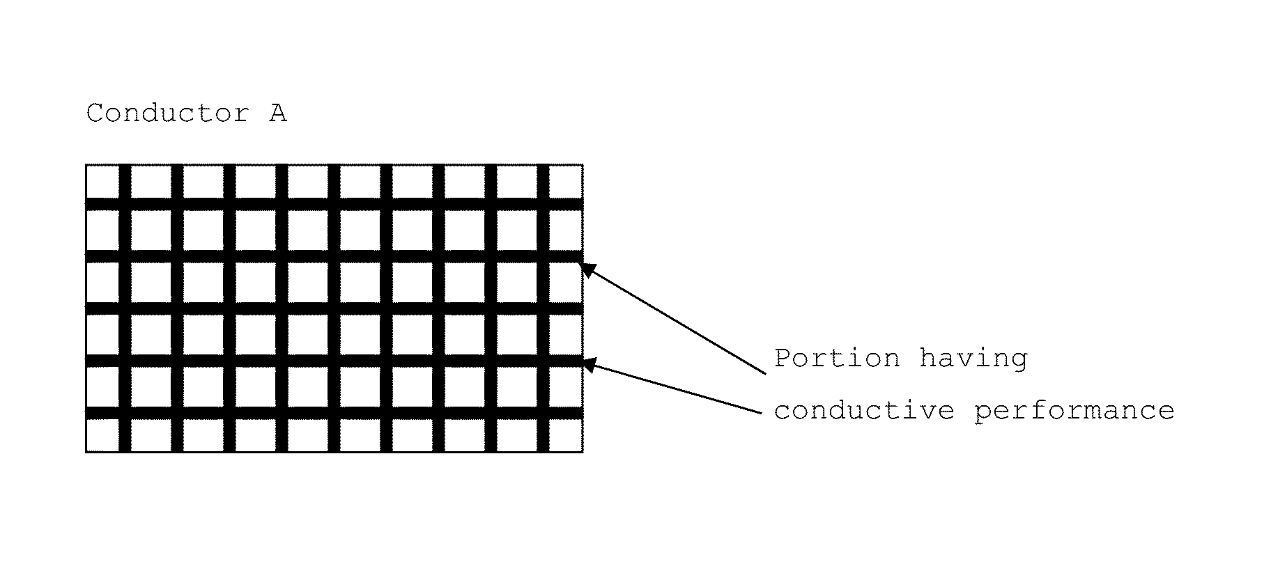
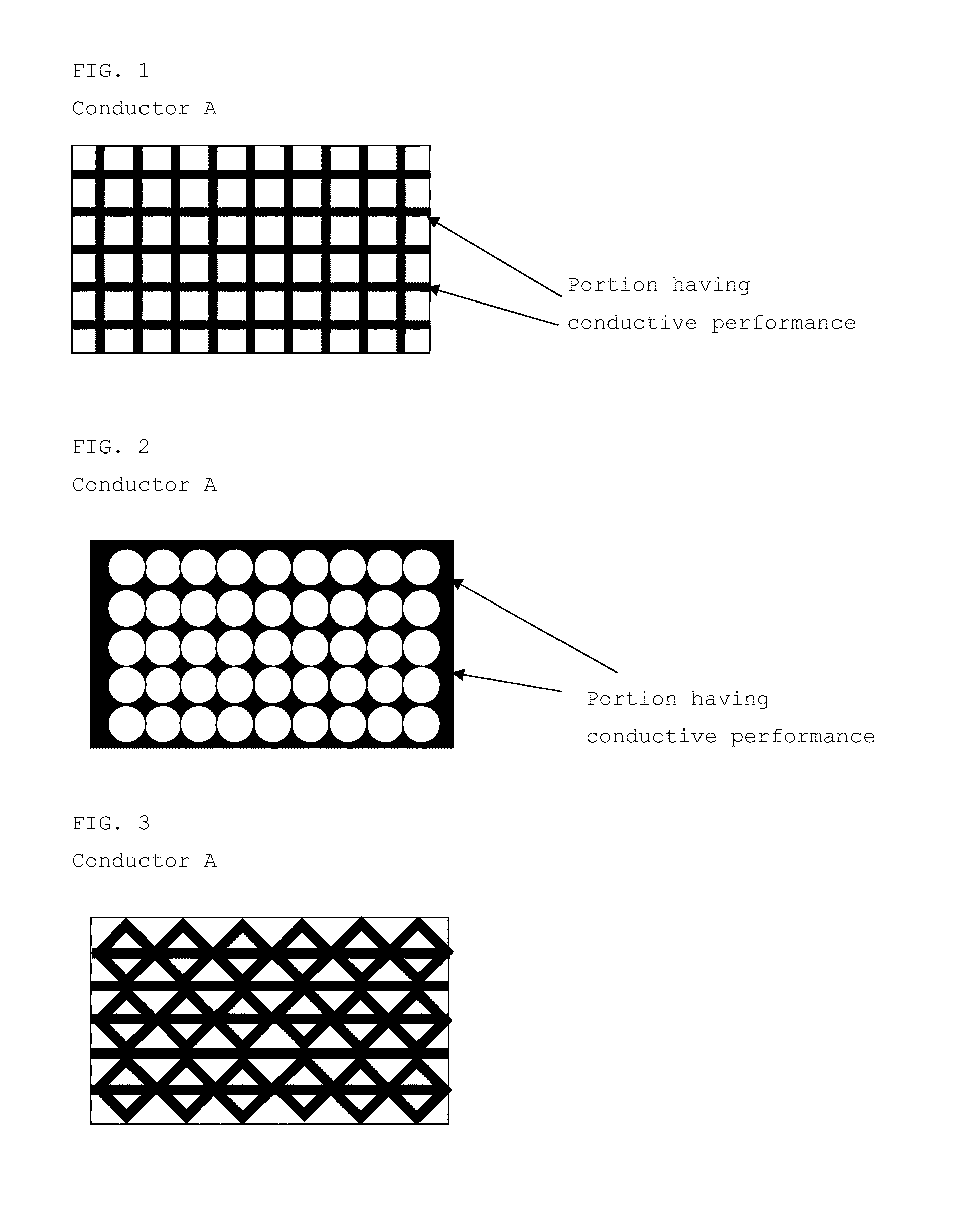
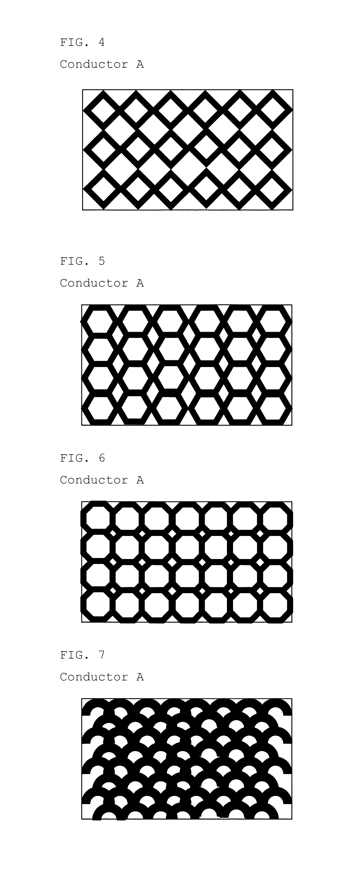
[0070]For the base material, a 2-mm thick low density polyethylene (PE) sheet (hard polyethylene sheet, manufactured by Shimonoseki Packing Co., Ltd., the same shall apply hereinafter) was used. As the conductor A, 9-μm aluminum foil stamped in a lattice form was laminated on one side of the base material. The lattice shape of the conductor A was such that the line width was 1 mm and the line spacing was 7 mm. As the conductor B, on the other side of the base material, 9-μm aluminum foil was laminated so as to cover the entire surface, to manufacture a communication sheet structure. The results are shown in Table 1.

example 2

[0071]For the base material, a 2-mm thick low density PE sheet was used. As the conductor A, aluminum was evaporated so as to be 350 angstroms in thickness on one side of the base material. The lattice shape of the conductor A was such that the line width was 1 mm and the line spacing was 7 mm. For evaporation, masking was performed so that the evaporating portion was in a lattice form, and then, evaporation was performed. As the conductor B, on the other side of the base material, aluminum was evaporated so as to be 350 angstroms in thickness, to manufacture a communication sheet structure. The results are shown in Table 1.

example 3

[0072]For the base material, a 2-mm thick low density PE sheet was used. As the conductor A, a silver paste (conductive paste DW-351H-30 manufactured by TOYOBO Co., Ltd., the same shall apply hereinafter) was printed in a lattice form so as to be 20 μm in thickness on one side of the base material. The lattice shape of the conductor A was such that the line width was 1 mm and the line spacing was 7 mm. As the conductor B, on the entire surface on the other side of the base material, a 20-μm thick silver paste was printed, to manufacture a communication sheet structure. The results are shown in Table 1.


PUM


Abstract

A communication sheet structure for transmitting electromagnetic waves, and thereby performing communication, is characterized in that the communication sheet structure includes a planar base material with a relative dielectric constant at a frequency of from 800 MHz to 10 GHz of from 1.0 to 15.0, and one side of the base material includes conductor A existing portion and non-existing portion, and the other side of the base material includes a conductor B existing over 90% or more thereof. The communication sheet structure enables communication in two dimensions, and the communication sheet structure is extremely excellent in communication performances.

Description

TECHNICAL FIELD[0001]The present invention relates to a communication sheet for performing communication by transmitting electromagnetic waves. More particularly, it relates to a communication sheet structure having two-dimensional expansion, optimum for, by contact or proximity of information communication devices with or to the surface thereof, performing communication with the communication devices, or for, in the case where a plurality of information communication devices are in contact with or in proximity to the surface thereof, relaying communication therebetween.BACKGROUND ART[0002]In recent years, use of computer communication networks or information networks represented by the Internet, has come into wide and popular use, and has been increasing without distinction among ordinary households, enterprises, and the like. The most common use form is such that personal computers and the like are directly connected with LAN cables, or connected by way of wireless to establish a ...

Claims


Application Information

Patent Timeline
Patent Type & Authority Patents(United States)
IPC IPC(8): H01Q1/36
CPCH04B13/00
Inventor TANAKA, AKIRAOOUCHIDA, MACHIKOMORI, HIROYUKI
Owner TEIJIN FRONTIER CO LTD
Why Eureka
Try Eureka