Temperature-based diagnostics method for a starter island

a technology of starter island and temperature-based diagnostics, which is applied in the direction of electric/dynamo-electric converter starters, control systems, dynamo-electric converter control, etc., can solve the problems of increasing the incidence of heat problems, affecting the maintenance effect, and presenting not much functionality for preventative maintenance purposes

Active Publication Date: 2019-12-17
SCHNEIDER ELECTRIC USA INC
View PDF13 Cites 0 Cited by
  • Summary
  • Abstract
  • Description
  • Claims
  • Application Information

AI Technical Summary

Problems solved by technology

Because overheating of starters and motors represents a large expense in lost energy, replacement costs, and downtime, etc. to the operator, preventive maintenance for the starters and motors is a practical necessity.
Increasing density in the physical placement of the starters may increase the incidence of heat problems.
However, this manner of protection is ad hoc and does not present much functionality for preventative maintenance purposes.

Method used

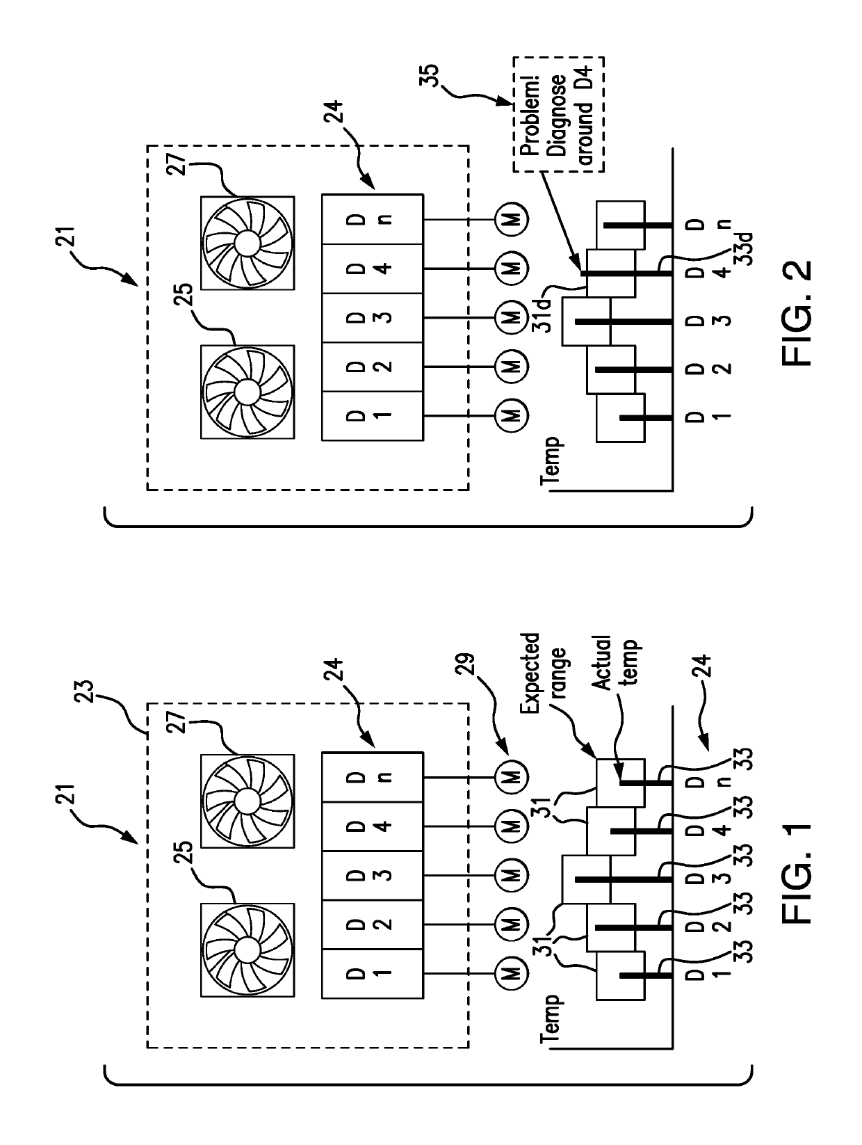
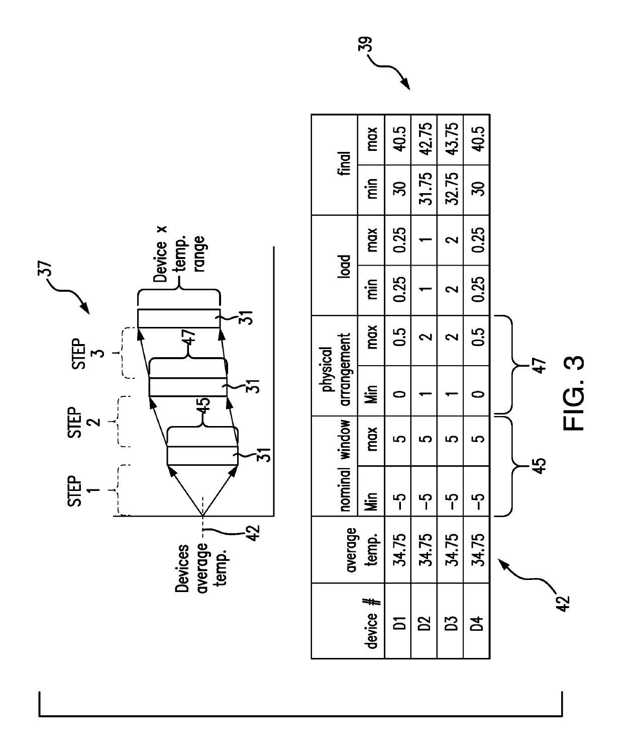
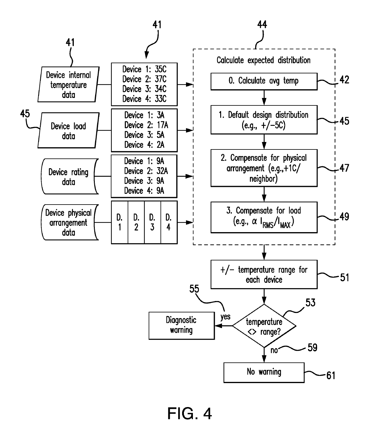

Image

  • Temperature-based diagnostics method for a starter island
  • Temperature-based diagnostics method for a starter island
  • Temperature-based diagnostics method for a starter island

Examples


second embodiment

[0027]FIG. 5 illustrates the invention whereby the same data is collected, but rather than absolute values, the temperature changes are tracked 63 against the change in operating load 65 over time whereby an expected correlation of temperature change from a change in operating load is developed 67. Further, as at step 66 indicated in both FIG. 5 and FIG. 6, while one can get along with the basic algorithm of FIG. 4 which just uses a + / −1° C. adjustment per neighbor, the algorithm for each embodiment may benefit by taking into account the temperature and / or current consumption of its neighbors, i.e. other motor starters grouped within the plurality of motor starters, in order to further refine the expected temperature range of the individual starters. In place of absolute values, the changes to these values may be used, since any of these values may affect the expected operating temperature range of the subject starter. Load and Operating Temperature of the starter are periodically a...

third embodiment

[0028]FIG. 6 illustrates the invention whereby the same data is collected as in the previous embodiment and the rate of temperature change 77 is also tracked as an indicator of starter system health. Load and Operating Temperature and rate of temperature change for the starter are periodically and routinely taken and compared to the recorded values for the starter and a range for rate of temperature change is developed 77. If the rate of change of the operating temperature is outside 79 of the normal range, a diagnostic warning 81 is issued to the operator of the starter island so that effective preventive maintenance or investigation may be begun. If the starter operating temperature is inside 83 of the correlation range, a diagnostic warning is not issued 85. This embodiment adds detection coverage for problems causing high rates of temperature change, but not necessarily temperatures that are out of range (e.g., an instantaneous drop of 20° C. may be within acceptable range, but ...


PUM


Abstract

A method of performing temperature-based diagnostics for motor starters within a physical grouping of motor starters is performed by determining a presently expected temperature operating range for each starter based on measuring operating temperatures of the starters; measuring their current draws, and evaluating the temperature and load draw data in light of compensation values assigned for the known power ratings of the starter and the starter's physical location within the grouping. With the presently expected temperature operating range of the starter determined, and the periodic monitoring of starter temperatures, when an individual starter's temperature exceeds its expected range, a diagnostic warning will be issued for that starter and / or for the control panel itself as a guide for preventative maintenance. Alternately, the warning may be issued for an unexpected temperature rise for a given rise in current draw, or for values exceeding an expected rate of temperature change.

Description

BACKGROUND OF THE INVENTION[0001]Field of the Invention[0002]The present invention relates to the management of preventative maintenance by diagnosing possible motor starter or industrial control panel problems through the monitoring the temperature behavior of motor starters in a group.[0003]Discussion of the Art[0004]A motor starter, also known as just a “starter,” is the control device dedicated to an electric motor and typically comprising an overload relay and a contactor, as is known in the art. A group of closely associated starters; located in proximity in the same environment is sometimes referred to as a “starter island.” It is often the case that a plurality of motors are grouped together in functional units to control several tasks within a function and there will be a plurality of starters grouped together in a common location such as in a cabinet remote from the motors. Examples may include a conveyor line with multiple sections, manufacture of an item with multiple op...

Claims


Application Information

Patent Timeline
Patent Type & Authority Patents(United States)
IPC IPC(8): H02P1/02H02H7/08H02H7/085H02P29/64H02P29/60H02P1/16
CPCH02H7/0852H02P29/64H02P1/022H02H7/0822H02H7/0855H02P29/60H02P1/16
Inventor JEFFERIES, KEVIN MEDWARDS, BENJAMIN WWHITE, MATTHEW LFREEMAN, ALAN EWEILER, RICHARD KARLFILIPPENKO, KONSTANTIN ALEXANDERLIPTAK, JULIUS MICHAEL
Owner SCHNEIDER ELECTRIC USA INC
Why Eureka
Try Eureka