Depth imaging device and driving method thereof

a technology of depth imaging and driving method, which is applied in the direction of image analysis, image enhancement, instruments, etc., can solve the problems of affecting the safety of the device, the detection of objects at different distances is more demanding, etc., and achieves the effect of reducing the range of the visual blind zone and saving power

Active Publication Date: 2019-12-24
LITE ON ELECTRONICS (GUANGZHOU) LTD +1
View PDF7 Cites 0 Cited by
  • Summary
  • Abstract
  • Description
  • Claims
  • Application Information

AI Technical Summary

Benefits of technology

[0005]The invention is directed to a depth imaging device, which has a reduced visual blind zone and a power-saving effect.
[0006]The invention is directed to a driving method for a depth imaging device, which implements an effect of a reduced visual blind zone and a power-saving effect.
[0017]According to the above description, in the depth imaging device and the driving method thereof, by setting the confidence threshold value and the distance threshold value in the predetermined range, the depth imaging device is adapted to switch the executed depth imaging system according to the distance between the object and the device itself, so as to reduce a range of a visual blind zone and achieve a power-saving effect.

Problems solved by technology

Particularly, detection of objects at different distances is more demanding, for example, an unmanned aerial vehicle, an aerial camera or a sweeping robot, etc.
However, both of the depth measurement methods have a situation of a blind zone in a particular area of a field of vision, and when the object is appeared in the blind zone, a related device cannot determine a distance of the object, which affects the safety of the device, and at the present stage where battery may only store a limited amount of electricity, how to mitigate the limitation of unable to measure the blind zone and maintain a system power-saving effect is an important effect to be achieved by present depth imaging device.

Method used


Image

  • Depth imaging device and driving method thereof
  • Depth imaging device and driving method thereof
  • Depth imaging device and driving method thereof

Examples


Embodiment Construction

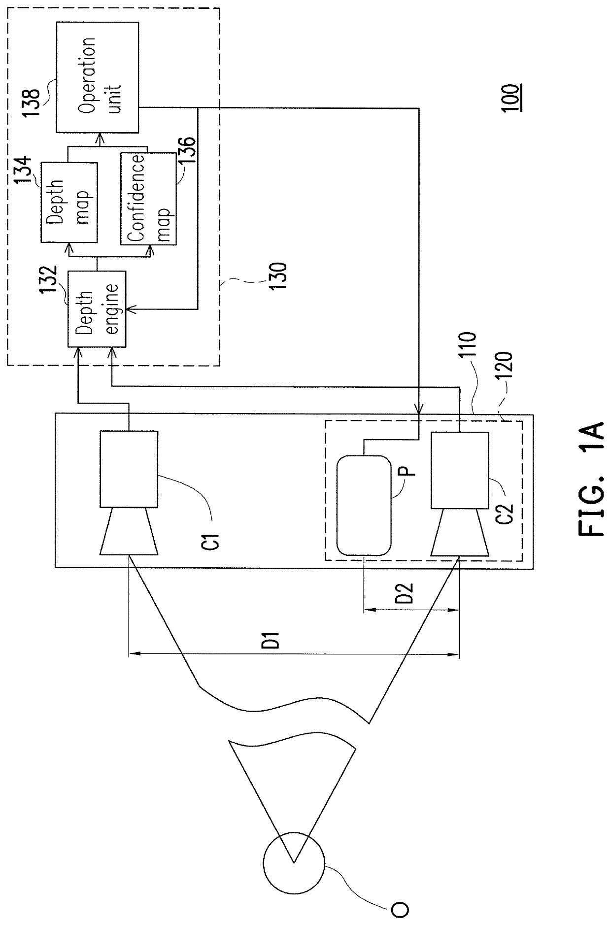
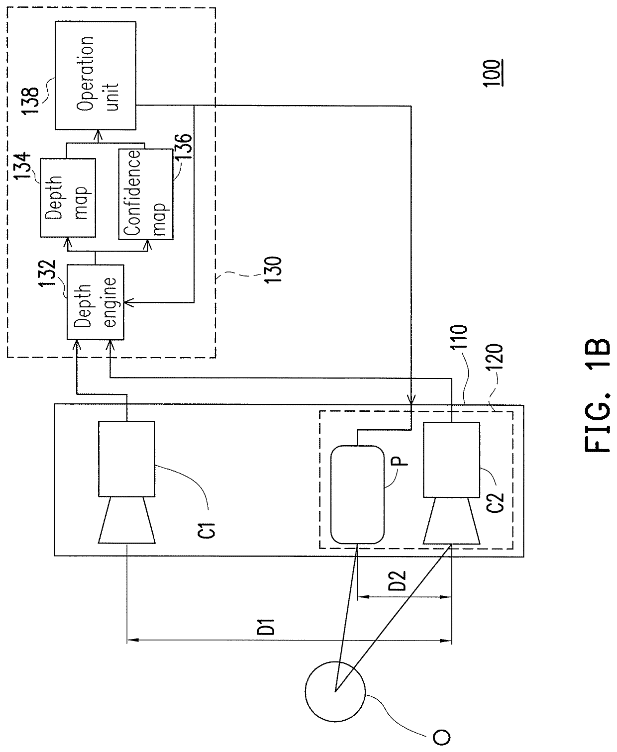
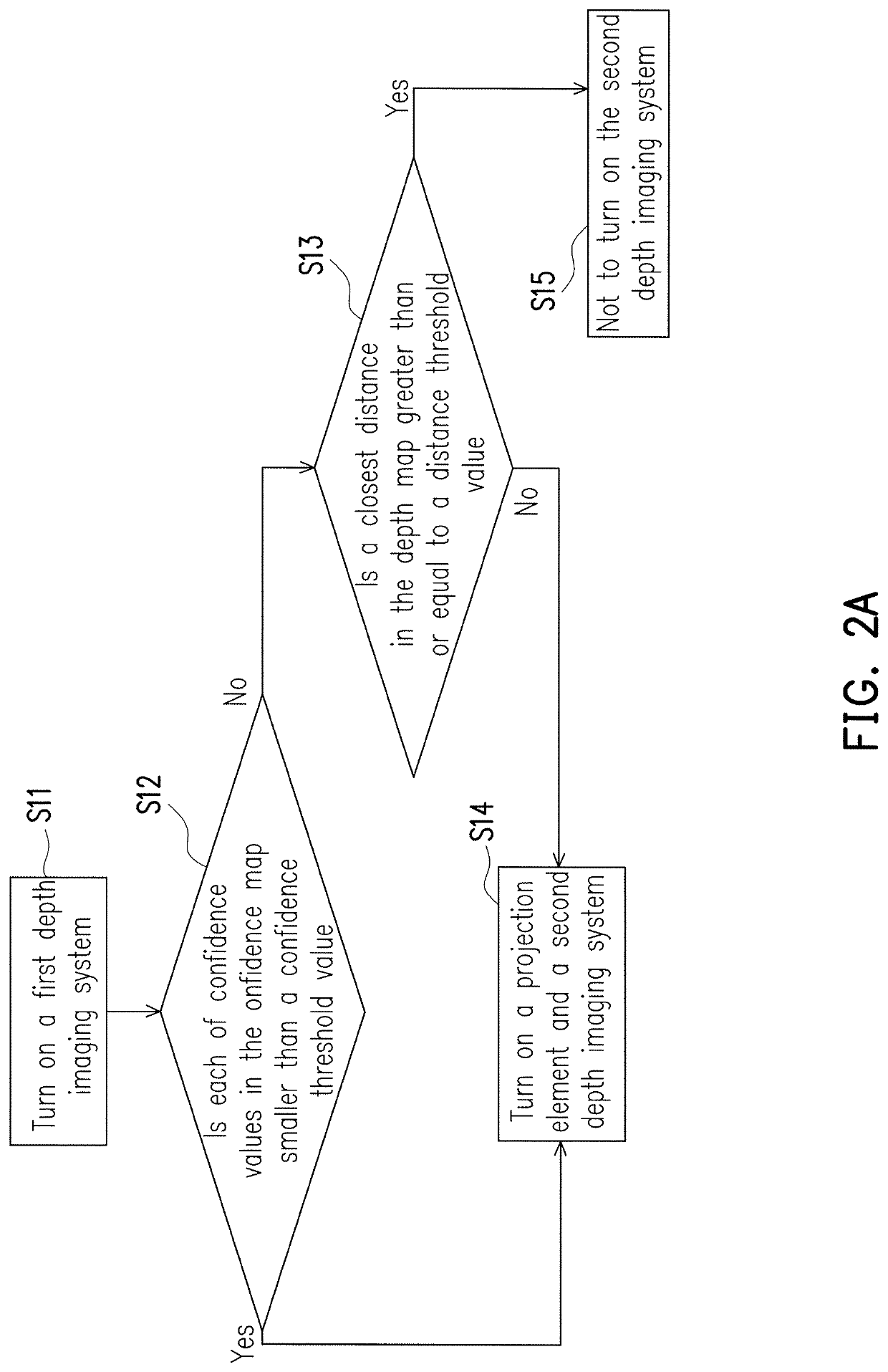
[0023]FIG. 1A is a schematic diagram of a depth imaging device turning on a first depth imaging system according to an embodiment of the invention. FIG. 2A is a flowchart illustrating a driving method of the depth imaging device of FIG. 1A.

[0024]Referring to FIG. 1A, in the present embodiment, the depth imaging device 100 includes a first camera C1, a second camera C2, a projection element P and a control unit 130. For example, in the present embodiment, the first camera C1 and the second camera C2 may be digital cameras having a photo-sensing element such as a charge-coupled device (CCD) or a complementary metal-oxide-semiconductor (CMOS), etc., where types of the first camera C1 and the second camera C2 may be the same or different. However, the invention is not limited thereto. In the present embodiment, the projection element P may be any projection element capable of projecting a structured light.

[0025]In the present embodiment, the first camera C1 and the second camera C2 form...


PUM


Abstract

A depth imaging device is provided. A first camera and a second camera form a first depth imaging system. A projection element and a second camera form a second depth imaging system. The control unit is configured to instruct one of the first and second depth imaging systems to acquire a depth map and a confidence map, and determine whether each of confidence values in the confidence map is less than a confidence threshold value. If each of the confidence values is less than the confidence threshold value, then the control unit turns on the other of the first and second depth imaging systems. If at least one of the confidence values is not less the confidence threshold value, then the control unit determines whether a closest distance in the depth map falls within a predetermined range or not. A driving method of a depth imaging device is also provided.

Description

CROSS-REFERENCE TO RELATED APPLICATION[0001]This application claims the priority benefit of China application serial no. 201711264915.3, filed on Dec. 5, 2017. The entirety of the above-mentioned patent application is hereby incorporated by reference herein and made a part of this specification.BACKGROUND OF THE INVENTIONField of the Invention[0002]The invention relates to an imaging device and a driving method thereof, and particularly relates to a depth imaging device and a driving method thereof.Description of Related Art[0003]Along with increasing demand on depth information of objects, a technique of accurately detecting object surface also becomes more and more important. Particularly, detection of objects at different distances is more demanding, for example, an unmanned aerial vehicle, an aerial camera or a sweeping robot, etc.[0004]At present, main measurement methods for obtaining depth information of objects are binocular vision, and structured light, etc. The binocular v...

Claims


Application Information

Patent Timeline
Patent Type & Authority Patents(United States)
IPC IPC(8): H04N13/239H04N13/271H04N13/254G06T7/593H04N13/00
CPCH04N13/254H04N13/271H04N13/239G06T7/593G06T2207/10028H04N2013/0081G06T7/521H04N23/60
Inventor WEI, SHOU-TECHEN, HSING-HUNG
Owner LITE ON ELECTRONICS (GUANGZHOU) LTD
Why Eureka
Try Eureka