
Vehicle air conditioning system for separately controlling flow of inside/outside air

a technology for air conditioning systems and vehicles, applied in vehicle heating/cooling devices, vehicle cleaning, vehicle components, etc., can solve the problems of increased thermal load of air conditioning, high possibility of window glass moisture generation, and inefficient heating performance, so as to improve heating performance, reduce the possibility of window glass moisture generation, and increase the inflow of inside air

Active Publication Date: 2020-01-07
HYUNDAI MOTOR CO LTD +2
View PDF26 Cites 2 Cited by
  • Summary
  • Abstract
  • Description
  • Claims
  • Application Information

AI Technical Summary

Benefits of technology

The present invention is an air conditioning system for a vehicle that solves two problems at the same time: improving heating performance by increasing the flow of inside air and reducing the buildup of moisture on the window glass.

Problems solved by technology

For this reason, an air conditioning thermal load is increased and heating performance becomes inefficient.
However, a conventional intake system has the following problems.
In this case, when inside air is mixed in quantity, heating performance is improved by a reduction in air conditioning thermal load, whereas there is a high possibility of the generation of moisture on the window glass due to the deterioration of the ventilation performance in the vehicle interior.
This moisture generation is one of frequent problems relating to air conditioning.
Increasing an amount of mixed inside air is advantageous to heating performance, but may cause the generation of moisture.
Moreover, the amount of mixed inside air should be increased considering a decreasing trend of engine coolant heat source for heating in recent years, but the amount of mixed inside air is not increased due to concerns about the generation of moisture.

Method used


Image

  • Vehicle air conditioning system for separately controlling flow of inside/outside air
  • Vehicle air conditioning system for separately controlling flow of inside/outside air
  • Vehicle air conditioning system for separately controlling flow of inside/outside air

Examples


Embodiment Construction

[0040]Reference will now be made in detail to various embodiments of the present invention(s), examples of which are illustrated in the accompanying drawings and described below. While the invention(s) will be described in conjunction with exemplary embodiments, it will be understood that the present description is not intended to limit the invention(s) to those exemplary embodiments. On the contrary, the invention(s) is / are intended to cover not only the exemplary embodiments, but also various alternatives, modifications, equivalents and other embodiments, which may be included within the spirit and scope of the invention as defined by the appended claims.

[0041]In the whole description, it will be understood that when a component is referred to as being “comprising” any component, it does not exclude other components, but can further comprises the other components unless otherwise specified.

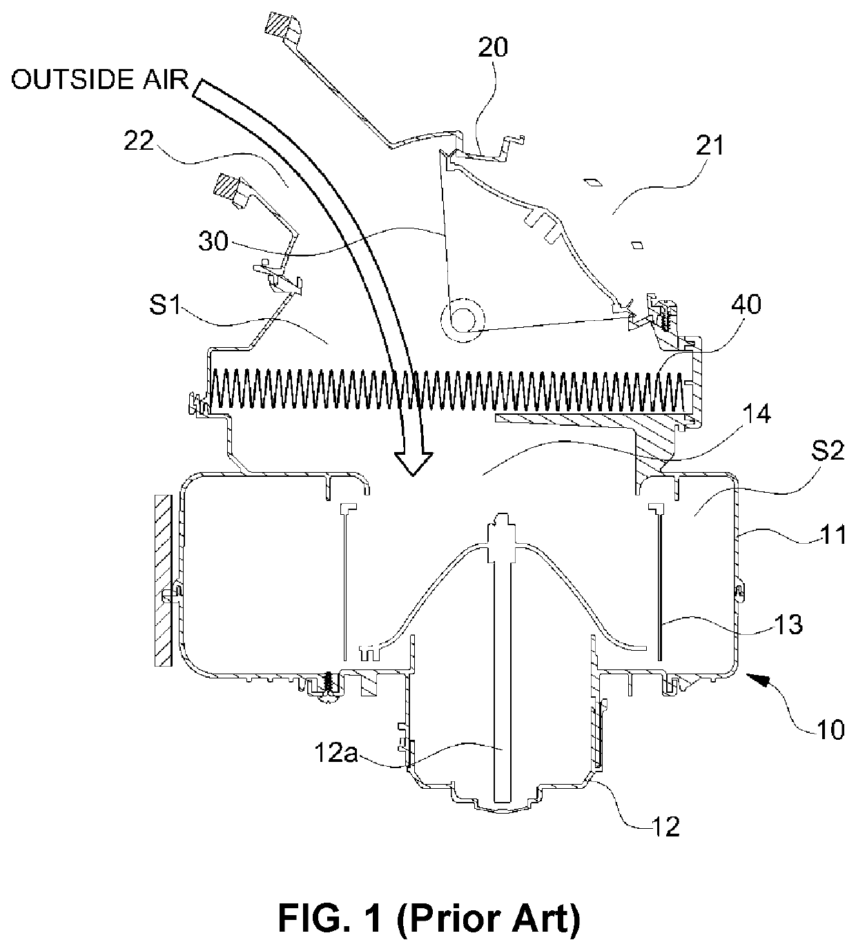
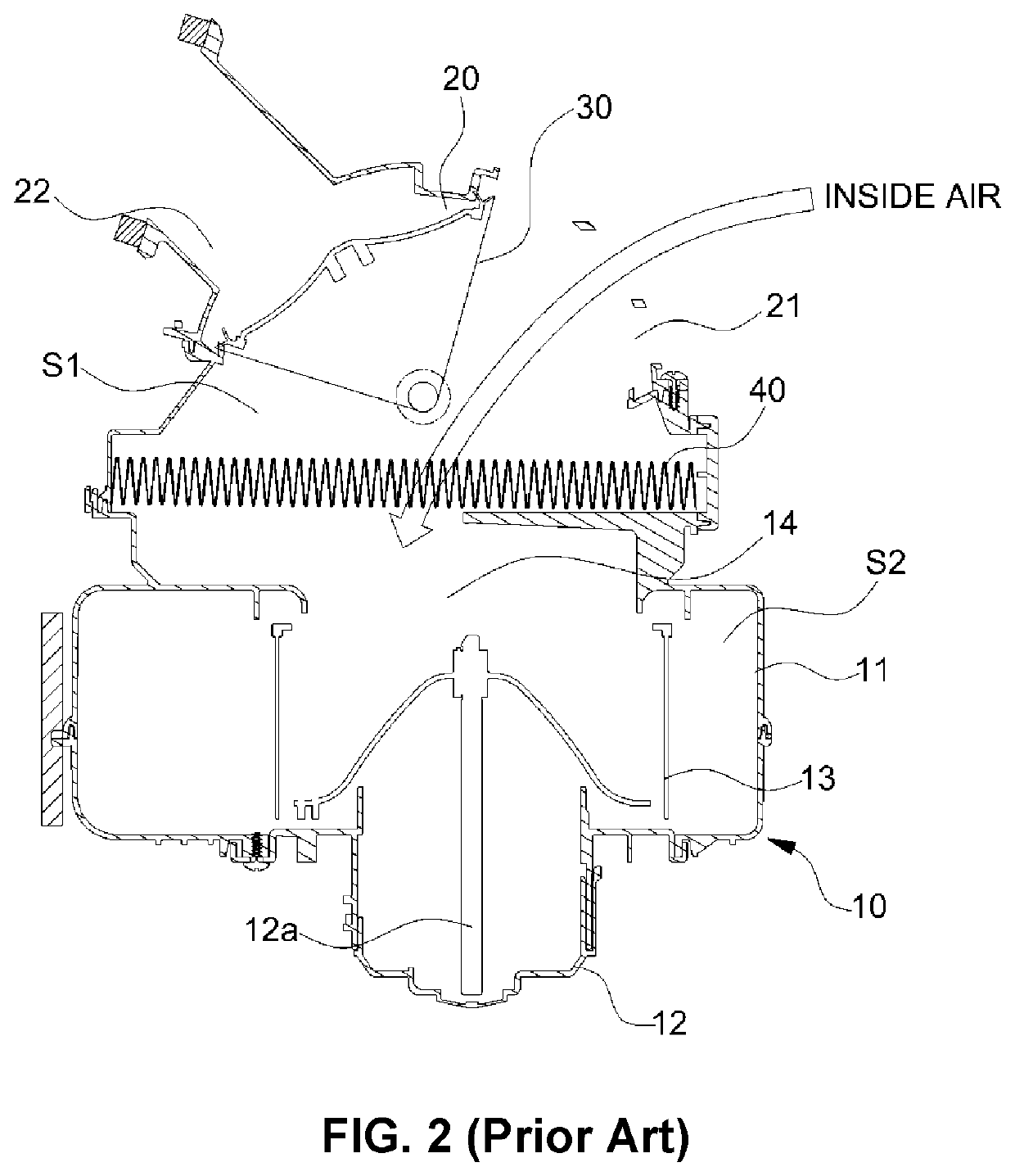
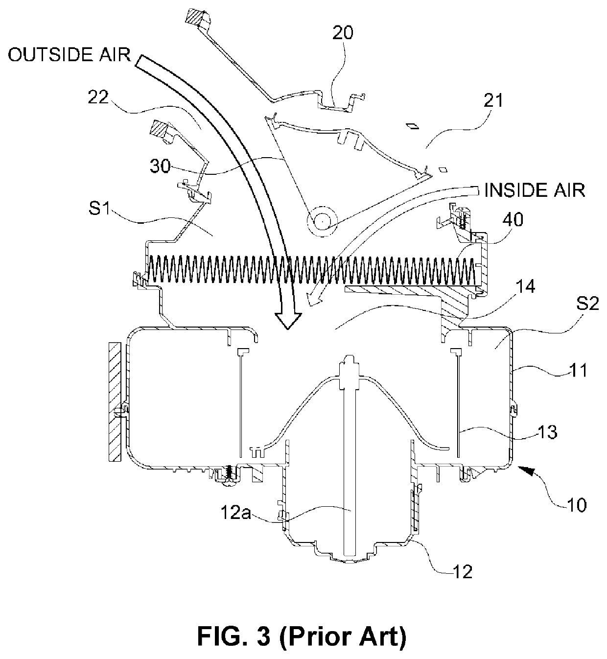
[0042]A conventional intake system will be first described to help the understanding of the ...


PUM


Abstract

Provided is an intake system of an air conditioning system for a vehicle, which is configured for simultaneously satisfying two conflict conditions of improving heating performance by increasing the inflow of inside air and of reducing the generation of moisture on a window glass, wherein a scroll case, in which a blower is mounted, is provided with a second partition member for dividing a passage, which is formed at an outlet port and includes a blower chamber around a blower fan, into an upper passage and a lower passage, and a flow guide for guiding air, which is separated by a first partition member and is introduced into the scroll case from an inlet case, to the respective upper and lower passages.

Description

CROSS-REFERENCE TO RELATED APPLICATION[0001]The present application claims priority to Korean Patent Application No. 10-2016-0117017 filed on Sep. 12, 2016, the entire contents of which is incorporated herein for all purposes by this reference.BACKGROUNDField of the Invention[0002]The present invention relates to an air conditioning system for a vehicle. More particularly, it relates to an air conditioning system for a vehicle, which is capable of simultaneously satisfying two conflict conditions of improving heating performance by increasing the inflow of inside air and reducing the generation of moisture on a window glass.Description of Related Art[0003]As known in the art, vehicles are equipped with HVACs (Heating, Ventilation, and Air Conditioning systems) for regulating interior temperatures and creating pleasant indoor environments.[0004]Such an HVAC cools or heats a vehicle interior by cooling or heating exterior air (outside air) introduced from the outside of the vehicle or...

Claims


Application Information

Patent Timeline
Patent Type & Authority Patents(United States)
IPC IPC(8): B60H1/00B60S1/54B60S1/02B60H1/02
CPCB60H1/00064B60S1/54B60S1/023B60H1/00678B60H1/00028B60H1/00471B60H2001/00607B60H2001/00135B60H1/00021B60H1/00271B60H2001/00092B60H2001/00085B60H1/00521B60H1/00671B60H1/00842B60H1/00849B60H2001/00185
Inventor LEE, YOON HYUNGJANG, BYEONG MOOKANG, MYUNG HUNBAE, JONG SIKJANG, CHUL MIN
Owner HYUNDAI MOTOR CO LTD
Learn More