Axial air gap rotating electric machine

a technology of rotating electric machines and air gap, which is applied in the direction of mechanical energy handling, windings, and magnetic circuit shapes/forms/construction, can solve the problems of reducing the life of bearings, and achieve the effect of ensuring the assembly of stators and reliably reducing shaft voltag

Active Publication Date: 2020-01-07
HITACHI IND EQUIP SYST CO LTD
View PDF12 Cites 2 Cited by
  • Summary
  • Abstract
  • Description
  • Claims
  • Application Information

AI Technical Summary

Benefits of technology

[0010]According to an aspect of the present invention, the assemblability of the stator is ensured and the shaft voltage is reliably reduced in the axial air gap rotating electric machine.

Problems solved by technology

An excessively large shaft voltage causes electrocorrosion of the bearing, thereby reducing the life of the bearing.

Method used


Image

  • Axial air gap rotating electric machine
  • Axial air gap rotating electric machine
  • Axial air gap rotating electric machine

Examples


first embodiment

Modification of First Embodiment

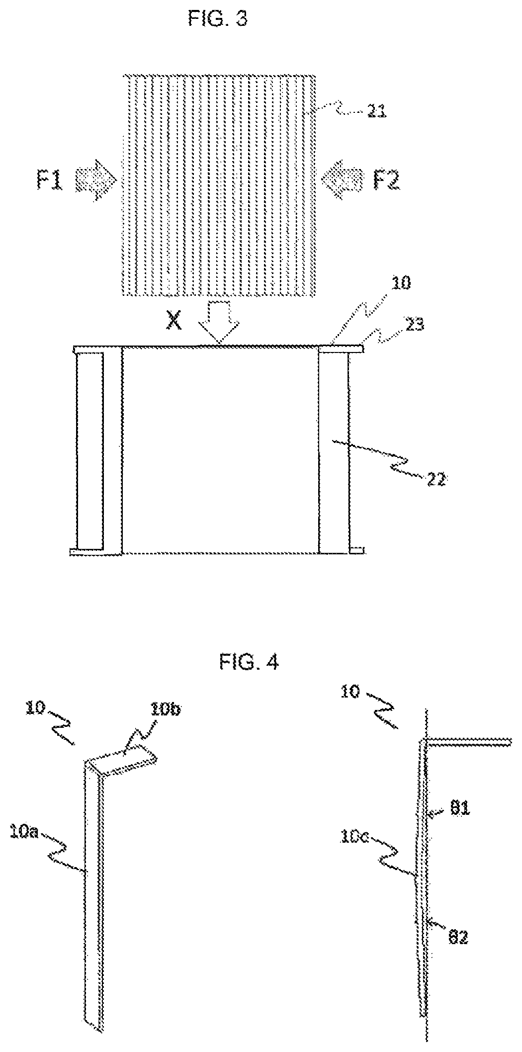
[0058]In the first embodiment, the conductive member 10 is formed by bending a rectangular conductor plate nearly at a right angle, but may have other shape as long as the conductive member 10 has the horizontal portion 10a and the vertical portion 10b.

[0059]FIG. 4 illustrates an example in which a bending angle between the horizontal portion 10a and the vertical portion 10b is 90 degrees or more, and a bending portion 10c is further provided to the horizontal portion 10a. In the figure, angles θ1 and θ2 are provided relative to a perpendicular from the vertical portion 10b. When a center part of the horizontal portion 10a is formed in such a shape, the conductive member 10 is plastically deformed along flat surfaces of the iron core 21 and the bobbin 23 when the iron core 21 is inserted. The conductive member 10 can apply larger contact pressure to the core 21.

[0060]The shapes of the horizontal surface and vertical surface of the conductive member 1...

second embodiment

[0063]FIG. 6A is a perspective view illustrating an entire stator core 25 for one slot in a rotating electric machine 1 according to a second embodiment. FIG. 6B is a perspective sectional view of the stator core 25.

[0064]In the second embodiment, a vertical portion 10b of a conductive member 10 has a hole 10e, and a protrusion portion 23d which is passed through the hole 10e is further provided to a flange portion 23b of a bobbin 23 so as to protrude to a rotor 30 side from the vertical portion 10b (see FIG. 6C). That is, a purpose of this is to suspend the conductive member 10 on the bobbin 23 stably.

[0065]An inner diameter of the hole 10e is substantially the same size as an outer diameter of the protrusion portion 23d. Both of them do not necessarily have sizes enough to fit the protrusion portion 23d into the hole 10e, and may have sizes enough to engage the protrusion portion 23d with the hole 10e. If there is some margin, an effect that the conductive member 10 can be easily ...

third embodiment

[0067]FIG. 7A is a perspective view illustrating an entire stator core 25 for one slot in a rotating electric machine 1 according to a third embodiment. FIG. 7B is a perspective sectional view of the stator core 25.

[0068]The stator core 25 of a fourth embodiment has a groove portion 23e which is provided over between both flange portions 23b on an inner diameter side of a tubular portion 23a of a bobbin 23, the inner diameter side facing a horizontal portion 10a of a conductive member 10 in a radial direction of a rotating shaft.

[0069]FIG. 7C is a partial sectional view of the bobbin 23 on a housing 50 side. The groove portion 23e has a width corresponding to a width of the horizontal portion 10a of the conductive member 10. The groove portion 23e is formed shallower than a thickness of the conductive member 10. That is, the conductive member 10 is provided to the bobbin 23 in a state where a vertical portion 10b is fitted into the groove portion 23d and is protruded from the groove...


PUM


Abstract

To ensure ready assembly of a stator and reliably reduce the shaft voltage in an axial air gap rotating electric machine, an axial air gap rotating electric machine has a circular ring-shaped stator formed by a plurality of stator cores arranged about a rotational axis direction in a ring shape. Each stator core comprises a tubular bobbin and a coil, with the tubular bobbin having an iron core inserted into a bobbin inner tubular portion substantially matching the peripheral shape of the iron core. The axial air gap rotating electric machine has a first conductive member having a horizontal portion and a vertical portion contacting the end surface of the bobbin opening portion. The horizontal portion contacts parts of the iron core outer peripheral surface and the inner peripheral surface of the bobbin inner tubular portion, and the vertical portion is conductively connected to the inner circumferential housing surface.

Description

TECHNICAL FIELD[0001]The present invention relates to an axial air gap rotating electric machine, and more particularly, to a structure of a stator of the axial air gap rotating electric machineBACKGROUND ART[0002]There are known axial air gap rotating electric machines in which a stator and a rotor plane-face each other with a predetermined air gap interposed therebetween in a radial direction of a rotating shaft. In addition to an advantage that the structure becomes thin (flat), the axial air gap rotating electric machine can increase a structural facing area between the stator and the rotator. Therefore, the axial air gap rotating electric machine has a structure suitable for high power density and high efficiency.[0003]As a stator used for such an axial air gap rotating electric machine, there are known structures disclosed in Patent Literature 1 and Patent Literature 2. Patent Literature 1 and Patent Literature 2 disclose an axial air gap rotating electric machine having a con...

Claims


Application Information

Patent Timeline
Patent Type & Authority Patents(United States)
IPC IPC(8): H02K3/34H02K21/24H02K7/08H02K1/18
CPCH02K21/24H02K3/34H02K7/088H02K1/182H02K3/521H02K5/1732H02K2203/12H02K11/33H02K11/40
Inventor TOKOI, HIROOKITAKAHASHI, SHUUICHIYONEOKA, YASUEISUZUKI, TOSHIFUMISAKAI, TORUYAMAZAKI, KATSUYUKIMASAKI, RYOUSOUIWASAKI, NORIHISAENOMOTO, YUJI
Owner HITACHI IND EQUIP SYST CO LTD
Why Eureka
Try Eureka