
chain tensioner

A chain tensioning device and chain technology, applied in the direction of transmission, belt/chain/gear, mechanical equipment, etc., can solve problems such as troublesome processing, and achieve the effect of easy processing and easy assembly

Inactive Publication Date: 2015-08-26
HONDA MOTOR CO LTD
View PDF5 Cites 0 Cited by
  • Summary
  • Abstract
  • Description
  • Claims
  • Application Information

AI Technical Summary

Problems solved by technology

[0006] However, if a structure in which the wedge-shaped part is in contact with the inner surface of the engine is used, in order to ensure that the wedge-shaped part can slide smoothly, necessary processing must be carried out on the part of the inner surface of the engine main body that is in contact with the wedge-shaped part. very troublesome

Method used


Image

  • chain tensioner
  • chain tensioner
  • chain tensioner

Examples


Embodiment Construction

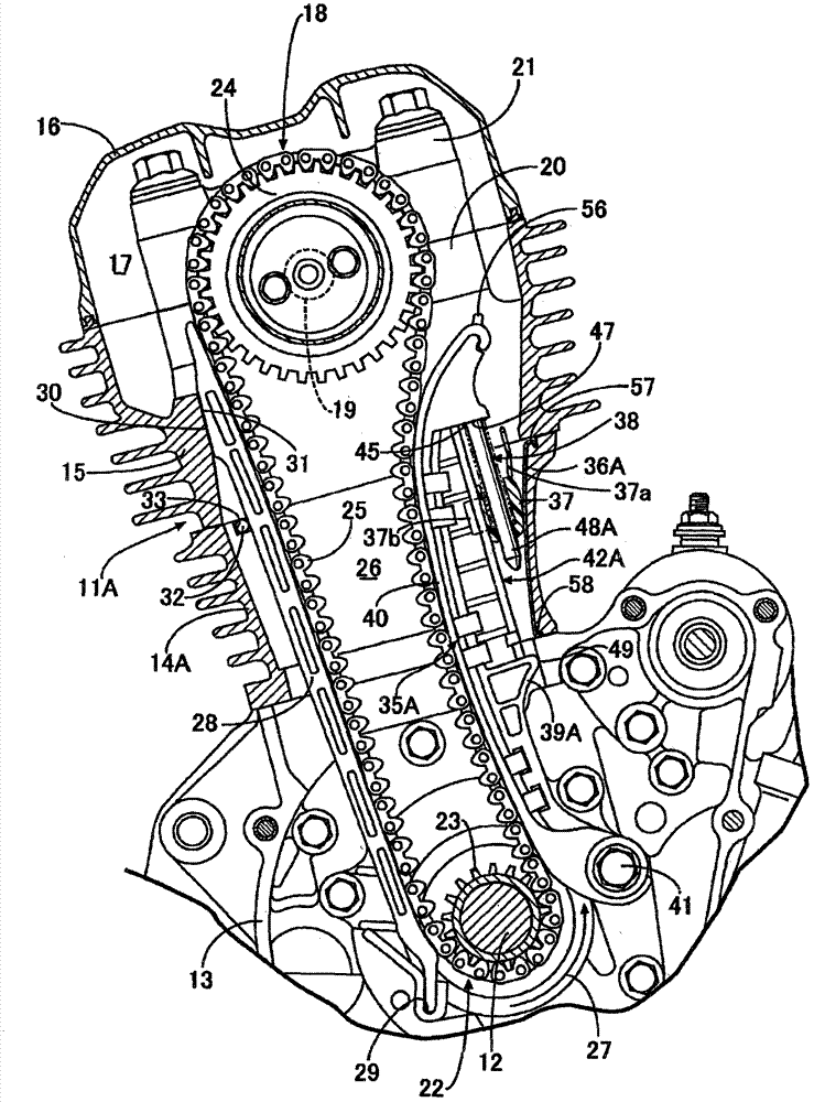
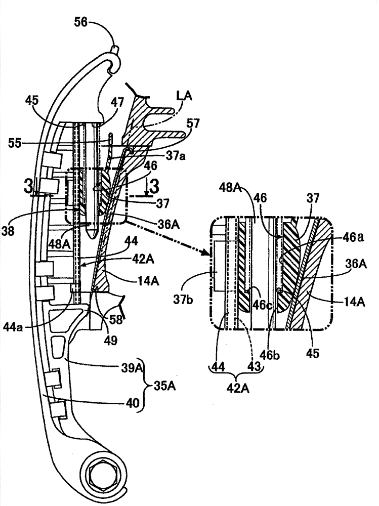
[0041] Refer below Figure 1 to Figure 5 A first embodiment of the present invention will be described. First, if figure 1 As shown, the engine involved in this embodiment is an engine equipped on a motorcycle, and its engine main body 11A has a crankcase 13, a cylinder assembly 14A, a cylinder head 15, and a cylinder head cover 16, wherein the crankcase 13 is rotatable The crankshaft 12 is supported on the ground, and the axis of the crankshaft 12 is consistent with the vehicle width direction of the motorcycle; the cylinder assembly 14A is connected with the crankcase 13 and is inclined forward and upward; the cylinder head 15 is connected with the cylinder assembly 14A; the cylinder head cover 16 It is connected with the above-mentioned cylinder head 15 to form a valve cavity 17 between it and the cylinder head 15 .

[0042] A valve mechanism 18 is housed in the valve chamber 17 . The valve mechanism 18 has a camshaft 19 whose axis is parallel to the above-mentioned crank...


PUM


Abstract

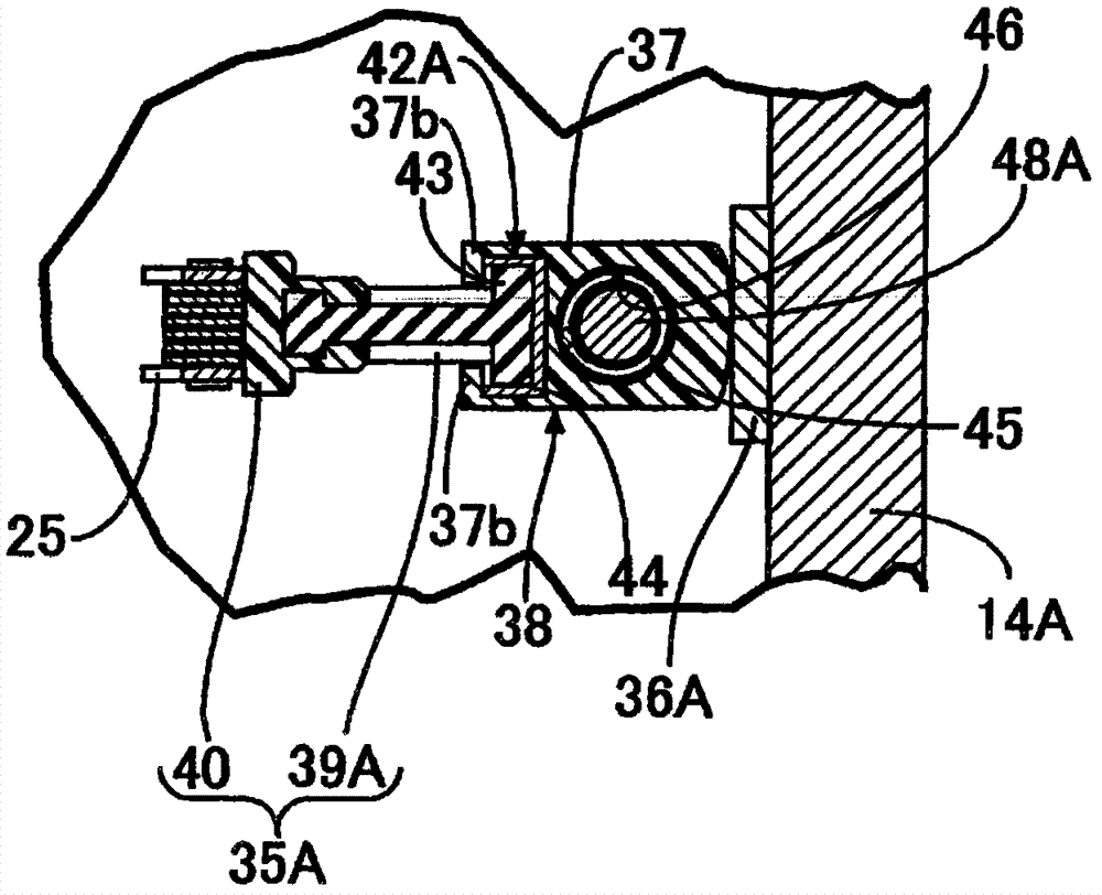
PROBLEM TO BE SOLVED: To structure a wedge receiving part for slide-contacting a wedge without requiring complicated processing on an engine body. SOLUTION: The chain tensioner device includes: tensioner arms (35A, 35B) of which one end part is rotatably supported by the engine bodies (11A, 11B) so as to slide-contact with an outer surface on a loose side of a cam chain (25) travelling on a chain passage (26) arranged on the engine bodies (11A, 11B); wedge receiving parts (36A, 36B, 62) fixedly arranged on an inner surface side of a part facing to the chain passage (26) out of the engine bodies (11A, 11B); and an energizing means (38) interposed between the wedge receiving parts (36A, 36B, 62) and the tensioner arms (35A, 35B), capable of moving so as to energize the tensioner arms (35A, 35B) to a side of the cam chain (25), and having the wedge (37) slide-contacting with the wedge receiving parts (36A, 36B, 62). The wedge receiving parts (36A, 36B, 62) are detachably mounted on the engine bodies (11A, 11B).

Description

technical field [0001] The present invention relates to a chain tensioning device, the chain tensioning device has a tensioning arm, a wedge-shaped component seat, and a loading mechanism, wherein a chain passage for the chain to pass is provided on the engine main body, and the chain moves through the chain passage, the above-mentioned One end of the tension arm is rotatably supported on the engine main body, and the tension arm is in sliding contact with the outer surface of the slack side of the chain; Surface side; the loading mechanism has a wedge-shaped member disposed between the tension arm and the wedge-shaped member seat and in sliding contact with the wedge-shaped member seat, and the wedge-shaped member can move to load the tension arm toward the side of the chain. Background technique [0002] Patent Document 1 discloses a chain tensioner in which a guide rod is supported on a tension arm of the chain tensioner, and the guide rod can swing (rotate). The tension...

Claims


Application Information

Patent Timeline
Patent Type & Authority Patents(China)
IPC IPC(8): F16H7/08
Inventor 河野直树渡边觉横谷登小山贵史川上拓郎
Owner HONDA MOTOR CO LTD
Learn More