Vehicle control system

a technology of vehicle control and control device, which is applied in the direction of control device, driver input parameter, vehicle components, etc., can solve the problems of discomfort of the vehicle operator, significant electric power consumption of the steering actuator, etc., and achieve the effect of smoothing the transition in the behavior of the steering devi

Active Publication Date: 2020-01-14
HONDA MOTOR CO LTD
View PDF9 Cites 0 Cited by
  • Summary
  • Abstract
  • Description
  • Claims
  • Application Information

AI Technical Summary

Benefits of technology

[0008]In view of such problems of the prior art, a primary object of the present invention is to provide a vehicle control system with an idle stop function that can minimize the power consumption of a steering system thereof, avoid unnecessary interruption of an idle stop operation, and minimize a deviation between a steering input from a steering wheel and a steering angle of steered wheels.
[0010]This arrangement allows the steering angle of the road wheel to be kept substantially fixed when the vehicle speed is between the first and second values in an early part of the idle stop operation by having the steering motor control unit perform the position keep control. The position keep control may be performed by supplying electric current to the steering motor so as to provide a braking force, or, alternatively, by operating the steering motor as a dynamic brake. Thereby, the road wheel is prevented from being steered at the start of the idle stop operation so that the deviation between the steering angle of the steering member and the steering angle of the road wheel can be minimized, and unnecessary canceling of the idle stop operation (which can occur as a result of a steering angle change greater than a prescribed threshold value) can be avoided.
[0013]Thereby, the supply of electric current to the steering motor can be terminated once the vehicle speed falls below the second value so that the power consumption by the steering motor is minimized. At this stage, the vehicle speed is so low that the resistance to the steering operation caused by the friction with the road surface is significant, and this minimizes any inadvertent steering movement of the road wheel.
[0015]Thereby, the deviation between the steering angle of the steering member and the steering angle of the road wheel can be minimized over the entire duration of the idle stop operation.
[0018]If the change of the steering input angle is in the direction to increase the steering angle from the value at the start of the idle stop operation, the engine restart threshold value is raised. This is advantageous because the driver of the vehicle is likely to anticipate an increase in the steering angle upon termination of the idle stop operation, and the saving of electric power consumption by the steering actuator can be maximized Conversely, if the change of the steering input angle is in the direction to decrease the steering angle from the value at the start of the idle stop operation, the engine restart threshold value is lowered. This is advantageous because the driver of the vehicle is not likely to anticipate a decrease in the steering angle upon termination of the idle stop operation, and is thereby prevented from experiencing any undesired impression although the saving of electric power consumption by the steering actuator can be slightly decreased.
[0024]Thereby, the transition in the behavior of the steering device can be made smoother.

Problems solved by technology

In such a steer by wire device, if the steering wheel is turned when the vehicle is stationary, the steering actuator consumes a significant amount of electric power.
More importantly, completely locking the steering shaft may cause discomfort to the vehicle operator.

Method used


Image

  • Vehicle control system
  • Vehicle control system
  • Vehicle control system

Examples


Embodiment Construction

)

[0033]A preferred embodiment of the present invention is described in the following with reference to the appended drawings.

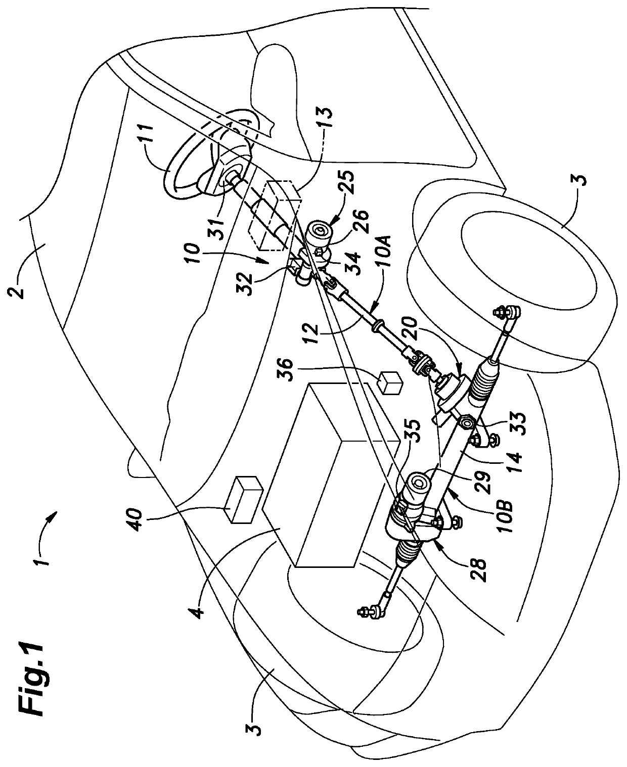
[0034]FIG. 1 is a see-through schematic perspective view of a front part of a vehicle according to an embodiment of the present invention. The vehicle 1 consists of a four-wheeled vehicle including a pair of front wheels 3 supported by a vehicle body 2 so as to be steerable via respective front suspension systems. An engine room is formed in the front part of the vehicle body 2, and a cabin is formed behind the engine room. An internal combustion engine 4 for powering the front wheels 3 is housed in the engine room. A driver's seat is provided on a front left side part of the cabin, and a steering device 10 for steering the front wheels 3 is provided between the driver's seat and the front wheels 3.

[0035]The steering device 10 includes a steering wheel 11 (or a steering member) arranged in front of the driver's seat to receive a steering input from the driver....


PUM


Abstract

In a steer by wire and idle stop vehicle, idle stop conditions for invoking an idle stop operation include that the traveling speed of the vehicle has fallen below a first value (10 km / h). When the vehicle speed is lower than the first value but higher than a second value (5 km / h), a steering actuator control unit 44 executes a position keep control whereby a steering motor 29 is electrically braked, and a reaction force actuator control unit 43 operates a reaction force motor 26 as a dynamic brake. When the vehicle speed has fallen below the second value in the idle stop operation, the steering motor control unit terminates the position keep control.

Description

TECHNICAL FIELD[0001]The present invention relates to a vehicle control system, and in particular, to a vehicle control system for a vehicle incorporated with a steer by wire device and configured to perform an idle stop operation.BACKGROUND ART[0002]Currently marketed passenger vehicles are often equipped with a steer by wire steering device in which front wheels are mechanically decoupled from a steering wheel, and steered by a steering actuator in response to the operation of the steering wheel. In a steer by wire steering device, a steering unit having a steering actuator for turning the front wheels and a reaction force actuator for applying a steering reaction force to a steering wheel is provided. In order to allow the steering operation to be performed at the time of a failure, the steering unit and the steering wheel can be connected to each other via a clutch which is normally disengaged but can be engaged when required.[0003]In such a steer by wire device, if the steering...

Claims


Application Information

Patent Timeline
Patent Type & Authority Patents(United States)
IPC IPC(8): B60W10/20B60W10/06B60W30/18
CPCB60W10/06B60W30/18054B60W10/20B60W2510/20B60W2710/065B60W2710/20B60W2422/50B60W2510/0642B60W2520/04B60W2520/10B60W2540/18B62D5/001B62D5/0463B62D6/001B60W10/02
Inventor KATAYAMA, HIROTAKAUEDA, YASUSHI
Owner HONDA MOTOR CO LTD
Why Eureka
Try Eureka