Method for precise synchronization of a combustion engine

a technology of combustion engine and synchronization method, which is applied in the direction of combustion engine, electric control, machines/engines, etc., can solve the problem of length of time, and achieve the effect of reducing the distance between the two synchronizations and estimating the intervals faster

Active Publication Date: 2020-01-14
VITESCO TECH GERMANY GMBH
View PDF22 Cites 1 Cited by
  • Summary
  • Abstract
  • Description
  • Claims
  • Application Information

AI Technical Summary

Benefits of technology

[0019]An estimated synchronization method makes it possible to obtain an estimated interval more quickly. So, it is appropriate to propose an exact synchronization method that is improved accordingly so as to be quicker, and thus reduce the distance between the two synchronizations.
[0020]The idea behind an aspect of the invention is to combine the two approaches, estimated synchronization and exact synchronization, and to use a continuous estimated interval from an estimated synchronization method to speed up the determining of an angular position using an exact synchronization method.

Problems solved by technology

Therefore, ascertaining the angular position of a marker indicates the angular position of the crankshaft but is not enough to indicate the angular position of the engine.
The chief disadvantage with this approach is the length of time it takes.

Method used


Image

  • Method for precise synchronization of a combustion engine

Examples


first embodiment

[0069] there are two scenarios considered.

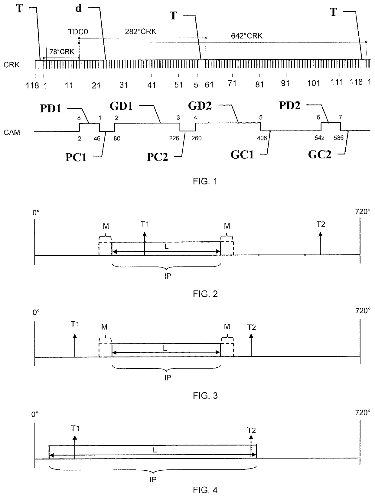
[0070]In a first scenario, illustrated in FIG. 2, if exactly one of the determined angular positions T1, T2 belongs to the estimated interval IP, in this case the position T1, then this angular position T1 is deemed to be the angular position of the engine. In this case, the estimated interval IP makes it possible to remove the indeterminacy, keeping just one angular position T1. This angular position T1 is known with precision. Exact synchronization is achieved and the method is finished.

[0071]The advantage of the method in terms of speed may be appreciated here. Specifically, in this favorable case, exact synchronization is achieved as soon as the first “marker” event is received, i.e. very quickly. With a typical crankshaft wheel performing two revolutions and comprising one marker per revolution, such an event occurs on average at 180° CRK, namely at one quarter of an engine cycle, and at the latest, at 360° CRK, namely at one half of an...

second embodiment

[0075] a tolerance margin M, featured in dotted line at the endpoints of the interval IP in FIGS. 2 and 3, is added to the estimated interval IP which is then replaced by the estimated interval IP increased by said tolerance margin M. The comparison is performed in a similar way, drawing the same conclusions.

[0076]The addition of this tolerance margin M, around the estimated interval IP, seeks to take account of the unknown that is the angular timing setting of the variable valve timing device or VVT. This is because this angular timing setting may have an influence on a camshaft event and thus may have modified the estimated interval IP, the determination of which is generally based on one or more camshaft events. So, this tolerance margin M is advantageously equal to a portion of the angular span of a variable-timing device. A preferential value of 75% of the angular span has yielded good results. Thus, for example, for a variable-timing device exhibiting an angular span of 55° CR...


PUM


Abstract

An exact synchronization method for determining an angular position of an engine, modulo one engine cycle, by a crankshaft sensor and of at least one camshaft sensor. The method includes: estimating a continuous estimated interval assumed to contain the angular position, on receipt of a “marker” event, determining an angular position corresponding to each one of the possible occurrences of this “marker”, comparing the determined angular position with the estimated interval. If exactly one of the determined angular positions belongs to the estimated interval, then this angular position is the angular position of the engine. And an engine control method using such a method.

Description

CROSS REFERENCE TO RELATED APPLICATIONS[0001]This application is the U.S. National Phase Application of PCT International Application No. PCT / EP2016 / 002093, filed Dec. 12, 2016, which claims priority to French Patent Application No. 1657374, filed Jul. 29, 2016 and U.S. Patent Application No. 62 / 268,934 filed Dec. 17, 2015, the contents of such applications being incorporated by reference herein.FIELD OF THE INVENTION[0002]The present invention relates to a method for synchronizing an engine. Synchronizing an engine is the operation that consists in determining the angular position of an engine. This determination is essential in order to be able then to control the engine and perform certain operations, such as fuel injection or ignition, at the right moment in the engine cycle.BACKGROUND OF THE INVENTION[0003]An engine, such as an internal combustion engine, includes a crankshaft sensor and at least one camshaft sensor.[0004]A crankshaft sensor comprises a crankshaft toothed wheel...

Claims


Application Information

Patent Timeline
Patent Type & Authority Patents(United States)
IPC IPC(8): F02D41/00F02D41/06F02D13/02F02D41/26
CPCF02D13/0215F02D41/009F02D41/26F02D41/062F02D2041/001F02D2041/0092F02D2400/08Y02T10/12
Inventor ZOUBOFF, PIERRELEFEVRE, JULIEN
Owner VITESCO TECH GERMANY GMBH
Why Eureka
Try Eureka