Controlling a fuel injection solenoid valve

a solenoid valve and fuel injection technology, applied in the direction of electric control, fuel injection apparatus, charge feed system, etc., can solve the problems of polarity reversal of voltage, inability to accurately control the injection process, and difficulty in actuation or inaccurate injection, so as to reduce inaccuracies or unreliability, and improve the injection process

Active Publication Date: 2020-01-14
VITESCO TECH GERMANY GMBH
View PDF14 Cites 0 Cited by
  • Summary
  • Abstract
  • Description
  • Claims
  • Application Information

AI Technical Summary

Benefits of technology

[0011]It is therefore an object of the present invention to provide a method and a device, in particular an engine control unit, which makes it possible to improve an injection process, in particular with regard to an injection quantity and a profile of the injection with respect to time, in relation to the prior art. In particular, it is an object of the present invention to reduce inaccuracies or unreliabilities owing to bouncing in a magnetic valve.
[0023]The first profile and the second profile may be representable or represented by a first curve and a second curve respectively in a coordinate system in which the current is plotted along one axis (for example the X axis) and the magnetic flux is plotted along another axis (for example the Y axis). Here, the magnetic flux may for example be calculated mathematically by means of the measured voltage and the measured current taking into consideration the ohmic resistance of the coil. Thus, the first profile and the second profile may be determined in a simple manner, and in particular also visualized and thus easily evaluated.
[0024]The first characteristic and the second characteristic may for example comprise a gradient (dψ / di) and / or a position (that is to say position of current or magnitude of current and magnitude of the magnetic flux) on the respective curve, in particular at least at the respective start of displacement, furthermore in particular along at least one section of an opening movement of the closure element between the start of displacement and a contact state in which the armature abuts against a pole piece in order to end the opening movement (for the first time). Here, the reference characteristic may comprise at least one reference gradient and / or one reference position. The respective characteristics are thus determined in a simple manner for example by means of mathematical curve sketching. The respective contact state may in this case represent the end of the opening movement. If bouncing occurs or would be expected to occur during the actuation in accordance with the first voltage profile, then the first contact state is regarded as the first abutment of the armature against the pole piece. It may be advantageous for bouncing that is expected to occur to be determined solely on the basis of the characteristic at the start of displacement, in order that a control intervention may be performed even before the opening of the magnetic valve in order to configure the second voltage profile such that the bouncing that is expected to occur is reduced.
[0027]It is thus possible for both the start of displacement and the contact state to be reliably located.
[0041]Embodiments of the present invention offer injector-specific actuation for the avoidance of bouncing processes and associated deficiencies in the quantity characteristic curves of the fuel. Thus, an equalization of quantity characteristic curve rail injectors is made possible.

Problems solved by technology

The short-circuiting of the coil results in a polarity reversal of the voltage owing to the dissipation of the magnetic field stored in the coil.
Furthermore, in the bouncing region, or during the bouncing movement, the injector actuation (in particular the actuation of the magnetic valve for the opening of the magnetic valve) may also be difficult or inaccurate, because a unique dependency of actuation duration (for example duration of the boost voltage and / or duration of a holding voltage interval) and the injection quantity will imperatively not always be present.
Thus, in conventional injection systems which use a magnetic valve, inaccuracies may arise with regard to the desired injection quantity of the fuel and also with regard to the desired characteristic of the injection of the fuel with respect to time.
The actuation is thus however subject to significant restrictions, which may have adverse effects on the operation of the internal combustion engine.

Method used


Image

  • Controlling a fuel injection solenoid valve
  • Controlling a fuel injection solenoid valve
  • Controlling a fuel injection solenoid valve

Examples


Embodiment Construction

[0054]The following description of the preferred embodiment(s) is merely exemplary in nature and is in no way intended to limit the invention, its application, or uses.

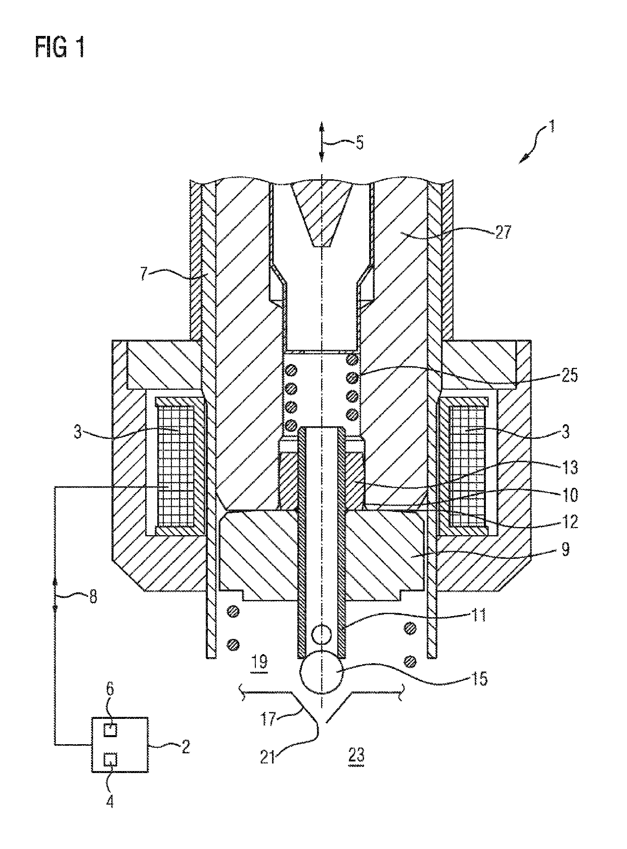
[0055]The magnetic valve 1 illustrated in a schematic sectional illustration in FIG. 1 has a coil 3 to which a voltage may be applied such that a current flow through the coil 3 occurs for the purposes of building up a magnetic field. Here, the magnetic field points substantially in a longitudinal direction 5 of a guide cylinder 7. The magnetic field acts on a ferromagnetic armature 9 which is displaceable within the guide cylinder 7. By means of displacement of the armature 9, a nozzle needle 11 or a closure element of the magnetic valve 1 may be displaced in the longitudinal direction 5, in particular as a result of contact of the armature 9 with a ring-shaped driver 13 which is fixedly connected to the closure element 11.

[0056]In the open state illustrated in FIG. 1, a closure ball 15 has been retracted out of a co...


PUM


Abstract

A device and a method are provided for controlling a magnetic valve which has a coil and an armature which is displaceable by magnetic force, by means of which armature a closure element is displaceable for the purposes of injecting fuel into a combustion chamber, the method includes the steps of: energizing the coil with a voltage in accordance with a first voltage profile in order to generate a first electrical current through the coil; determining a first profile as a function of a first magnetic flux and the first current; identifying, in the first profile, a first characteristic of at least one first start of displacement at which the armature begins to displace the closure element, generating a second voltage profile and energizing the coil in accordance with the second voltage profile, such that, in a second profile, as a function of a second magnetic flux and a second current, a second characteristic of a second start of displacement is more similar to a reference characteristic than the first characteristic.

Description

CROSS-REFERENCE TO RELATED APPLICATIONS[0001]This application claims the benefit of PCT Application PCT / EP2016 / 058089, filed Apr. 13, 2016, which claims priority to German Patent Application 10 2015 206 729.7, filed Apr. 15, 2015. The disclosures of the above applications are incorporated herein by reference.FIELD OF THE INVENTION[0002]The present invention relates to a method and a device for controlling a magnetic valve for injecting fuel into a combustion chamber. In particular, the present invention relates to an engine control unit which is designed to control a fuel injection magnetic valve.BACKGROUND OF THE INVENTION[0003]A magnetic valve or a solenoid injector may be used for injecting fuel into a combustion chamber, for example into a cylinder. A solenoid injector of this type (also referred to as coil-type injector) has a coil which generates a magnetic field when current flows through the coil, whereby a magnetic force is exerted on an armature such that the armature is d...

Claims


Application Information

Patent Timeline
Patent Type & Authority Patents(United States)
IPC IPC(8): F02D41/20F02M61/16F02M63/00F02M51/06
CPCF02D41/20F02M63/0015F02M63/0007F02M63/007F02M51/061F02M61/161F02D2041/2055F02D2041/2058F02D2041/2051F02D2041/2037
Inventor HAUSER, CHRISTIANRÖSEL, GERDSTUTIKA, MARKUS
Owner VITESCO TECH GERMANY GMBH
Why Eureka
Try Eureka