
Automatic monitoring device for marine crank

An automatic monitoring and cranking technology, which is applied in the direction of combustion engine, engine control, engine components, etc., can solve the problems of response delay, high maintenance cost, and detection accuracy drop, and achieve accurate receiver position, simple device structure, and high control accuracy Effect

Active Publication Date: 2021-12-03
ANQING MARINE ELECTRIC DEVICE
View PDF6 Cites 0 Cited by
  • Summary
  • Abstract
  • Description
  • Claims
  • Application Information

AI Technical Summary

Problems solved by technology

[0006] In this case, since the device for detecting the angular position of the crankshaft needs to be installed on the crankshaft and one side of the crankshaft, and the temperature inside the cylinder body is relatively high, the entire device is easily affected by high temperature, resulting in reduced service life and low detection accuracy. Gradually decline over time, it is very troublesome in subsequent maintenance and replacement, and the maintenance cost is very high;
[0007] In addition, during the continuous operation of the crank and crankshaft, multiple angle data will be calculated corresponding to each revolution, and the ignition and fuel injection will be controlled when the fuel injection advance angle and ignition advance angle are reached. This process requires real-time calculation of data, so it will Cause response delay, miss the best fuel injection and ignition timing

Method used


Image

  • Automatic monitoring device for marine crank
  • Automatic monitoring device for marine crank
  • Automatic monitoring device for marine crank

Examples


Embodiment 1

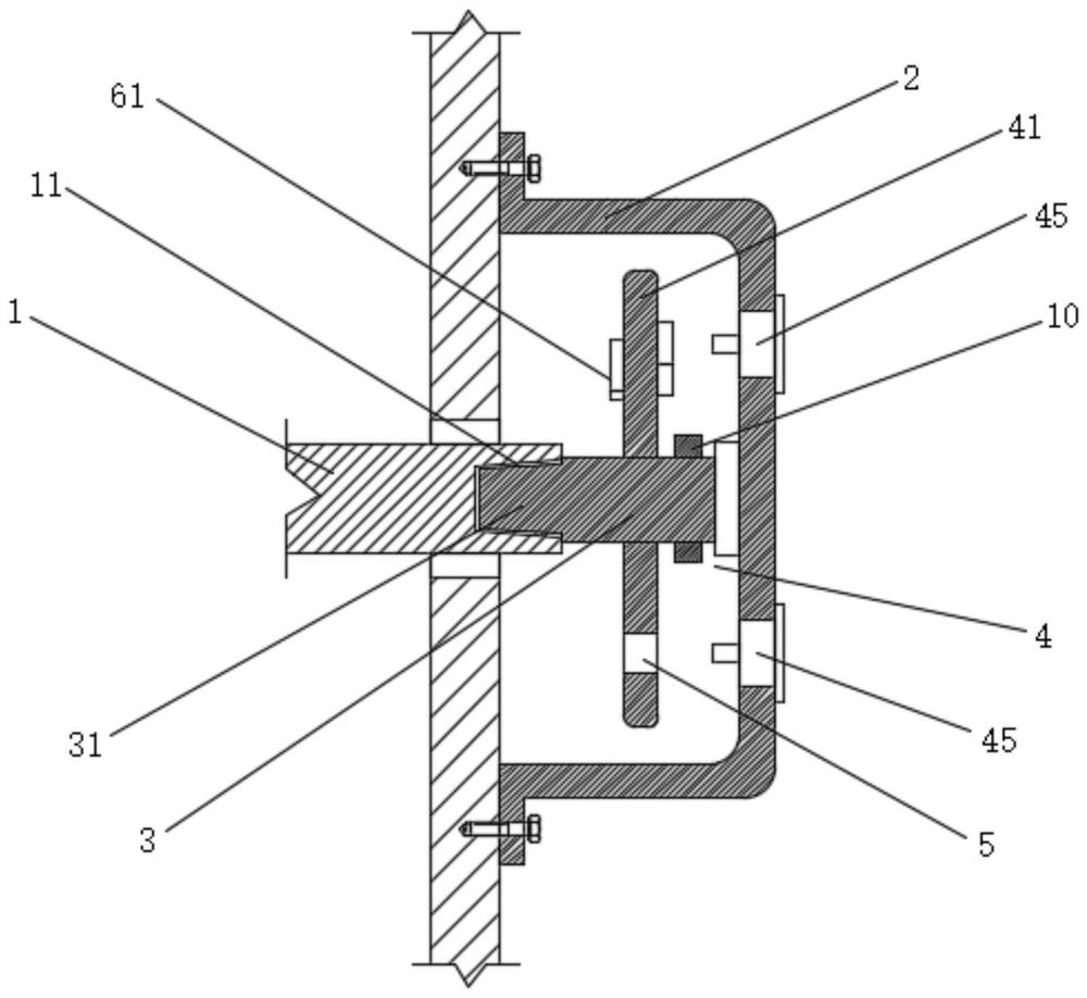
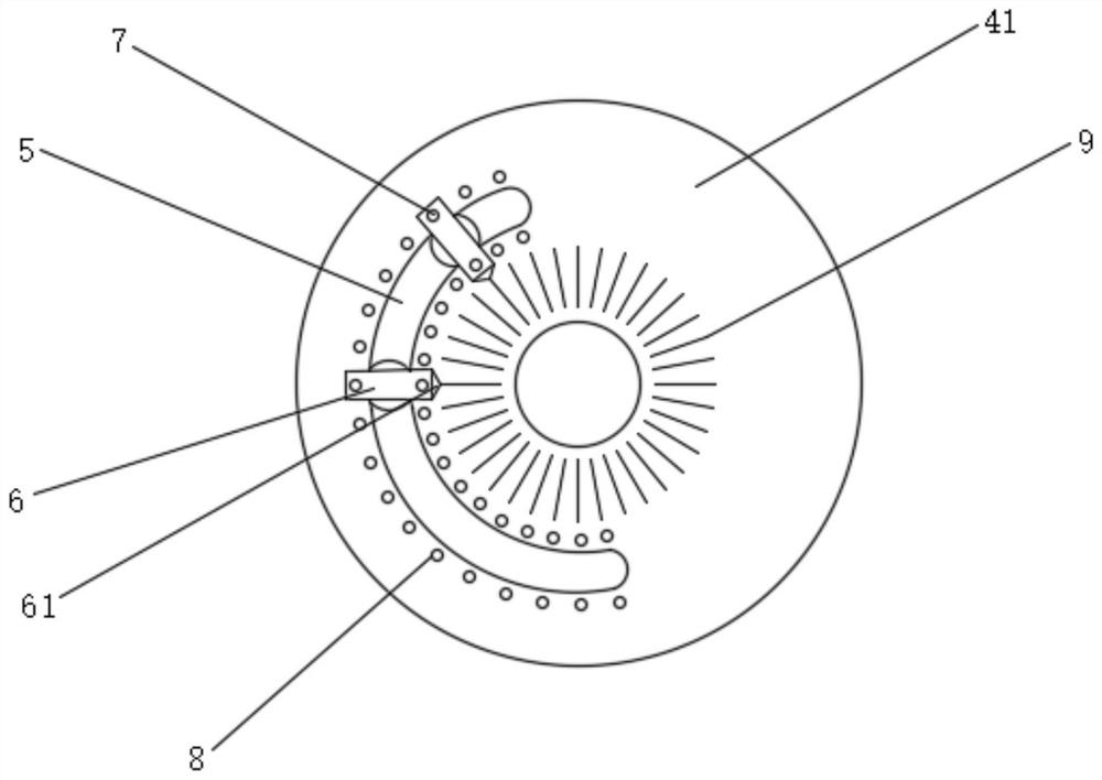
[0036] Such as Figure 1-4 As shown, a marine crank automatic monitoring device includes:

[0037] Crankshaft 1, the tail end of which extends to the outside of the machine body and a slot 11 is opened on the end surface of the tail end;

[0038] Mounting cover 2, which covers the outside of the crankshaft 1 tail end and is installed on the body; the mounting cover 2 is made of transparent plastic, the edge of the mounting cover 2 is fixed with a mounting plate, and the mounting plate can be connected to the body through screws The connection is disassembled, and the plug 31 is fully inserted into the slot 11 when the mounting plate is attached to the body;

[0039] Rotating shaft 3, one end of which is fixedly provided with a plug 31 that is engaged with the slot 11, and the other end is connected to the mounting cover 2 through a bearing. ;

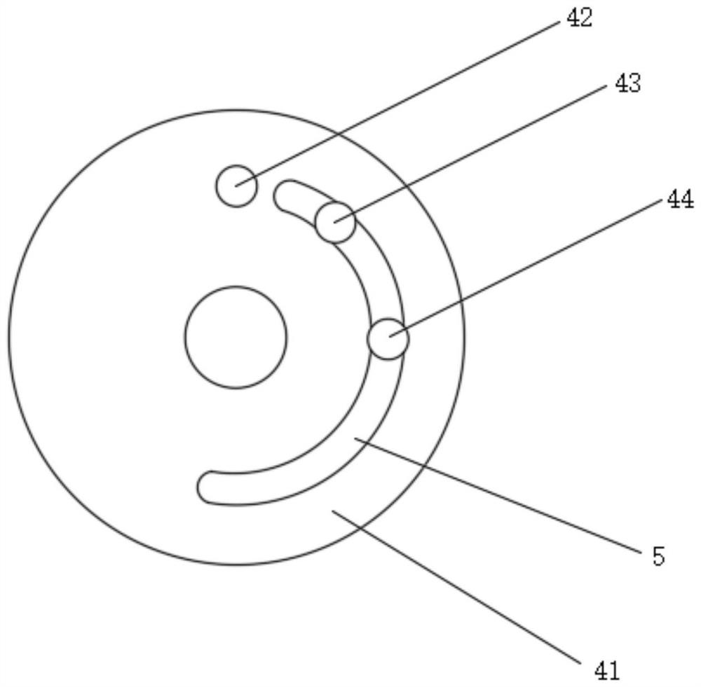
[0040] The crank monitoring assembly 4 includes a detection plate 41 fixed on the rotating shaft 3, a top dead center receiver 42 i...


PUM


Abstract

The invention relates to an automatic monitoring device for a marine crank. The automatic monitoring device comprises a crankshaft, a mounting cover, a rotating shaft and a crank monitoring component, wherein the tail end of the crankshaft extends to the outer side of the machine body and is provided with a slot; the mounting cover covers the tail end of the crankshaft and is installed on the machine body; one end of the rotating shaft is fixedly provided with a plug clamped with the slot, and the other end of the rotating shaft is connected with the mounting cover through a bearing; and the crank monitoring component comprises a detection plate fixed to the rotating shaft, a top dead center receiver, an ignition starting point receiver, an oil injection starting point receiver and two laser emitters, wherein the top dead center receiver, the ignition starting point receiver and the oil injection starting point receiver are installed on the detection plate and located on the same circular track, and the two laser emitters are installed on the inner side wall of the mounting cover and correspond to the two end points of the vertical diameter of the circular track respectively. The device can simultaneously control igniters and oil sprayers above two groups of alternately operating pistons, and the whole device is simple in structure, free of mass data computing, high in response speed and long in service life.

Description

technical field [0001] The invention belongs to the field of diesel engine crank monitoring devices, in particular to a marine crank automatic monitoring device. Background technique [0002] In order to detect the crank angle position of the engine, a ring gear is mounted on the crankshaft, and a plurality of convex parts (teeth) at equal intervals are provided on the ring gear, and a tooth-missing part for determining the reference position of the crankshaft is formed at one place and make it an unequal interval. When the engine is running, the convex part and the concave part are measured, and the ratio between them is used to identify the missing tooth part, that is, the reference position, so that the crank angle can be detected. Fuel injection timing and ignition timing are controlled based on the measured crank angle. [0003] The fuel injection time can be obtained by detecting the fuel injection advance angle, and the ignition time can be obtained by detecting the...

Claims


Application Information

Patent Timeline
Patent Type & Authority Applications(China)
IPC IPC(8): F02B77/08F02D43/00
CPCF02B77/08F02B77/087F02D37/02Y02T10/40
Inventor 李灿赵晓骏叶冰冰王良恩
Owner ANQING MARINE ELECTRIC DEVICE
Learn More