Variable compression engine
A compression ratio, engine technology, applied in engine control, machine/engine, mechanical equipment, etc., can solve problems such as lag, and achieve the effect of increasing power, saving fuel, and scientifically transmitting force
- Summary
- Abstract
- Description
- Claims
- Application Information
AI Technical Summary
Problems solved by technology
Method used
Image
Examples
Embodiment 1
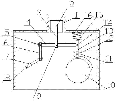
[0024] Such as figure 1 As shown, a variable compression ratio engine includes a piston 1, a connecting rod and a crankshaft 8, the connecting rod includes an upper connecting rod 3 and a lower connecting rod 6, the upper end of the upper connecting rod 3 is connected to the piston 1 through a piston pin 2, and the upper The lower end of the connecting rod 3 is connected with the crossbeam 4 through the connecting rod pin 9; one end of the crossbeam 4 is connected with the upper end of the lower connecting rod 6 through the left pin 5, and the lower end of the lower connecting rod 6 is connected with the crankshaft 8 through the connecting rod journal; the crossbeam The other end of 4 is connected with control rod 13 by right pin 14, and the upper end of control rod 13 is provided with an elastic member, and the lower end of control rod 13 has a groove, is provided with a cross pin 12 in the groove, and wheel 11 is connected with cross pin 12 by cross pin 12. The lower end of ...
Embodiment 2
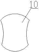
[0029] The structural difference between Embodiment 2 and Embodiment 1 is that the cam 10 adopts different shapes, and the shape of the cam 10 is as follows: image 3 As shown, the left and right sides of the cam 10 are concave arc surfaces, and the upper and lower sides are convex arc surfaces. Other structures are the same as in Embodiment 1.
[0030]The working process of the present embodiment is: the diameter setting of one circle of rotation of the crankshaft 8 is much larger than the stroke of the piston 1 . When the crankshaft 8 turns from bottom to top until the crank 7 forms a certain angle with the lower connecting rod 6, the piston 1 also runs to the highest point. If the crankshaft 8 continues to turn upwards in this case, the piston will continue Running upward will push off the cylinder head. In order to avoid this situation, the design of cam 2 is adopted. Entering the exhaust stroke, the crankshaft 8 rotates from bottom to top. When the crankshaft 8 rotates ...
Embodiment 3
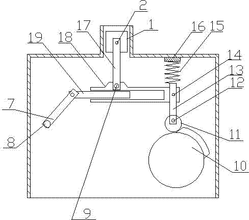
[0032] Such as figure 2 As shown, a variable compression ratio engine includes a piston 1, a connecting rod 17 and a crankshaft 8. The piston 1 is connected to the upper end of the connecting rod 17 through the piston pin 2, and the lower end of the connecting rod 17 is connected to the outer beam 18 through the connecting rod pin 9. connection, the outer beam 18 is provided with an inner cavity with an open end, and an inner beam 19 matching it is provided in the inner cavity, and the inner beam 19 can move left and right in the inner cavity of the outer beam 18, and the outer end of the inner beam 19 passes through the connecting rod journal Connected to the crankshaft 8, the length of the inner beam 19 exposed outside the outer beam 18 will elongate or shrink with the movement of the connecting rod journal; the other end of the outer beam 18 is connected with the control rod 13 through the right pin 14, and the control rod 13 The upper end is provided with an elastic membe...
PUM
 Abstract
Description
Claims
Application Information
 - R&D
- Intellectual Property
- Life Sciences
- Materials
- Tech Scout
- Unparalleled Data Quality
- Higher Quality Content
- 60% Fewer Hallucinations
Browse by: Latest US Patents, China's latest patents, Technical Efficacy Thesaurus, Application Domain, Technology Topic, Popular Technical Reports.
© 2025 PatSnap. All rights reserved.Legal|Privacy policy|Modern Slavery Act Transparency Statement|Sitemap|About US| Contact US: help@patsnap.com


