Torsional vibration damper

a torsional vibration and damper technology, applied in the direction of springs/dampers, rotating vibration suppression, gearing, etc., can solve the problems of limited sun gear size and limited vibration damping performance, and achieve the effect of enhancing the vibration damping performance of the torsional vibration damper, and increasing the design freedom of inertial mass

Active Publication Date: 2020-01-14
TOYOTA JIDOSHA KK
View PDF10 Cites 4 Cited by
  • Summary
  • Abstract
  • Description
  • Claims
  • Application Information

AI Technical Summary

Benefits of technology

[0008]Aspects of the present disclosure have been conceived noting the foregoing technical problems, and it is therefore an object of the present invention is to improve vibration damping performance of the vibration damper by increasing a design freedom of an inertial mass.
[0012]Thus, according to the embodiment of the present application, the first gear is held in the holding member. The first engagement member situated in an opposite side of the fluid coupling is meshed with the second gear rotated integrally with the input member to which the engine torque is applied, and the second engagement member situated between the holding member and the fluid coupling is meshed with the third gear rotated integrally with one of the output member and the inertial mass. The other of the output member and the inertial mass rotated integrally with the holding member. That is, the input member, the output member, and the inertial mass may be arranged in tandem in the axial direction of the torsional vibration damper. According to the embodiments of the present application, therefore, the inertial mass may be arranged between the member for transmitting torque through the clutch and the fluid coupling without being restricted by the input member and the output member. In other words, a design freedom of the inertial mass may be increased so that the inertial mass may be enlarged to enhance vibration damping performance of the torsional vibration damper.
[0013]In addition, the inertial mass may be connected to the third gear to be rotated integrally therewith. In this case, the pitch circle diameter of the second engagement member meshed with the third gear may be increased to be larger than that of the first engagement member to which the torque of the input member is applied. Consequently, a change in an angular velocity of the inertial mass resulting from pulsation of the torque delivered to the output member may be increased to further enhance the vibration damping performance of the torsional vibration damper.

Problems solved by technology

However, in the damper device taught by JP-A-2008-164013, a size of the sun gear is limited to a space enclosed by the plate member connecting the ring gear to the output member and the disk.
For this reason, the vibration damping performance of the sun gear may be limited.

Method used


Image

  • Torsional vibration damper
  • Torsional vibration damper
  • Torsional vibration damper

Examples


first embodiment

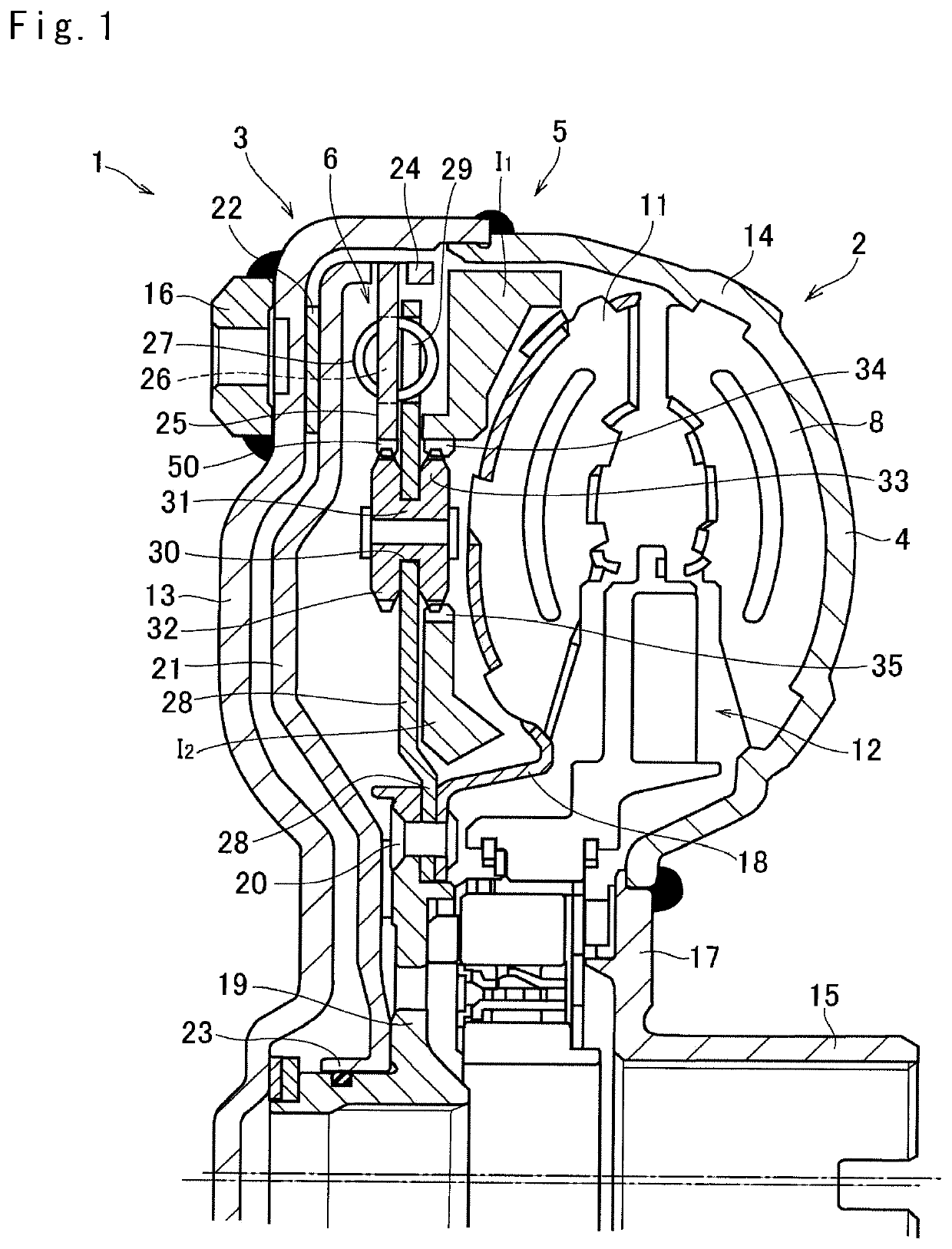
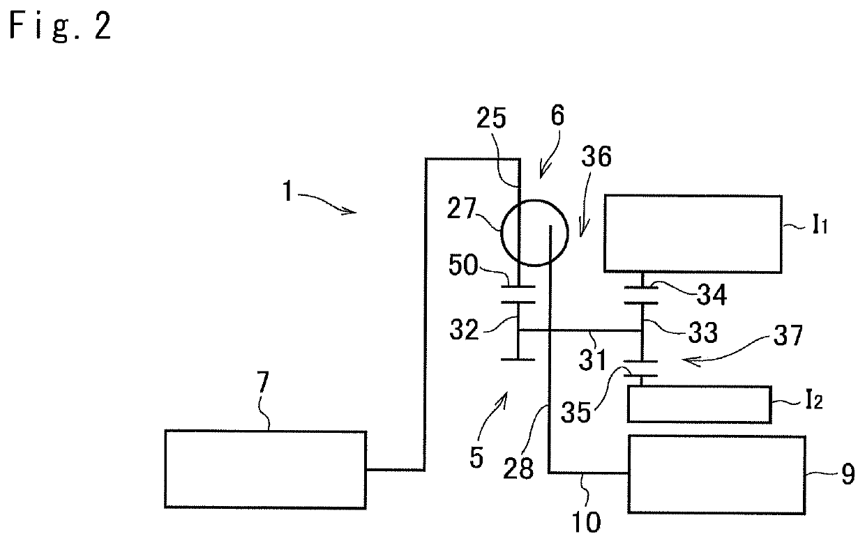
[0025]Preferred embodiments of the present application will now be explained with reference to the accompanying drawings. Referring now to FIG. 1, there is shown a cross-section of a torsional vibration damper 1 and FIG. 2 is a schematic diagram of the torsional vibration damper 1. The torsional vibration damper 1 comprises a torque converter 2 and a torque converter clutch 3 that enables torque transmission without passing through the torque converter 2, and an inerter damper 5 and a spring damper 6 are held in a housing 4 of the torque converter 2.

[0026]The torque converter 2 as a fluid coupling comprises a pump impeller 8 to which torque of an engine 7 is applied, a turbine runner 11 connected to an input shaft 10 of a transmission 9 while being opposed to the pump impeller 8, and a stator 12 interposed between the pump impeller 8 and the turbine runner 11.

[0027]The housing 4 includes a front cover 13 to which the torque of the engine 7 is applied, a pump shell 14 integrated wit...

second embodiment

[0051] a third cylindrical portion 38 is formed on the driven plate 21 protruding toward the first output plate 28 in an inner circumferential side of the shaft 31, and an annular second disc 39 is formed on a leading end of the third cylindrical portion 38. A plurality of first cutouts (not shown) individually having a predetermined length in the circumferential direction are formed on an inner circumferential end of the second disc 39 in a circular manner at predetermined intervals, and the second apertures 29 of the first output plate 28 are situated at positions to be congruent with the first cutouts.

[0052]According to the second embodiment, an annular second output plate 40 is arranged adjacent to the first output plate 28 while keeping a predetermined clearance therebetween, and the second disc 39 is situated between the first output plate 28 and the second output plate 40. A plurality of second cutouts (not shown) individually having a same length as that of the first cutout ...

fifth embodiment

[0060]In the torsional vibration damper 1 according to the present application, the inertial mass may also be connected to the element other than the second pinion gear 33. Turning to FIG. 10, there is schematically shown the torsional vibration damper 1 in which a third inertial mass 13 is connected to an annular carrier plate 43. The annular carrier plate 43 serves as the holding member. In the following explanation, common reference numerals are allotted to the elements in common with the foregoing embodiments, and detailed explanations for the common elements will be omitted.

[0061]According to the fifth embodiment, a fifth cylindrical portion 44 protrudes from an outer circumferential end of the driven plate 21 toward the turbine runner 11, and an annular third disc 45 is connected to an intermediate portion of the fifth cylindrical portion 44. The third disc 45 is also connected a third output plate 46 through the coil springs 27. A plurality of cutouts (not shown) individuall...


PUM


Abstract

A torsional vibration damper having enhanced damping performance is provided. A first gear held in the holding member includes a first engagement member situated in an opposite side of a fluid coupling and a second engagement member situated between a holding member and the fluid coupling. A second gear is meshed with the first engagement member, and a third gear is meshed with the second engagement member. The second gear is integrated with the input member, the third gear is integrated with the inertial mass, and the holding member is integrated with the output member.

Description

CROSS-REFERENCE TO RELATED APPLICATIONS[0001]The present invention claims the benefit of Japanese Patent Application No. 2016-062143 filed on Mar. 25, 2016 with the Japanese Patent Office, the disclosures of which are incorporated herein by reference in its entirety.BACKGROUND[0002]Field of the Disclosure[0003]Embodiment of the present disclosure relates to the art of a vibration damper for suppressing torsional vibrations resulting from torque pulses, by an inertia torque of a mass.[0004]Discussion of the Related Art[0005]JP-A-2008-164013 describes a damper device for absorbing vibrations resulting from pulsation of torque transmitted from an engine to a transmission through a torque converter clutch. The damper device taught by JP-A-2008-164013 comprises, a annular disk to which torque is delivered from the torque converter clutch, an output member to which the torque of the disk is delivered through spring, a sun gear connected to an inertial mass, a ring gear arranged around the...

Claims


Application Information

Patent Timeline
Patent Type & Authority Patents(United States)
IPC IPC(8): F16H45/02F16F15/12
CPCF16F15/1206F16H45/02F16F15/1202F16H2045/0268F16H2045/002F16H2045/0221F16H2045/0278
Inventor NAKAMURA, TAIKITAKAHASHI, YUYAMATSUMOTO, MORIHIROTSUKANO, FUSAHIRO
Owner TOYOTA JIDOSHA KK
Why Eureka
Try Eureka