Washpipe seal assembly

a technology of seal assembly and washpipe, which is applied in the direction of sealing/packing, borehole/well accessories, construction, etc., can solve the problems of uneven grease distribution, under- or over-filling of the seal assembly with grease, and reducing the possibility of sealing being forced through, so as to simplify assembly and simplify cross-section. , the effect of durabl

Active Publication Date: 2020-01-21
CLARK SEALS
View PDF16 Cites 3 Cited by
  • Summary
  • Abstract
  • Description
  • Claims
  • Application Information

AI Technical Summary

Benefits of technology

[0016]In one embodiment, the seal assembly of the disclosure includes a high pressure seal, e.g., a Viton D90 ring with a PTFE sealing surface located in a steel ring having a simple cross-section. Identical rings and seals are stacked three high, which simplifies assembly as compared to the differently shaped first, second, and third elastomeric v-ring seals and bronze spacer rings of the prior art. The high pressure seal of the disclosure has a self-lubricating polymer inner surface, such as PTFE or Teflon that eliminates difficulties associated with greasing the seal assembly through a grease port. Difficulties associated with greasing a seal assembly through a grease port include underfilling or overfilling the seal assembly with grease and uneven grease distribution. The high pressure elastomeric seal that is received within a ring defines an inner leg for contacting a washpipe and defines an outer leg in contact with the ring. The inner leg, outer leg, and seal base define a seal cavity. A seal insert ring, such as an o-ring, is received within the seal cavity for directing pressure process toward the seal base for mitigating a spreading force that may otherwise act on the elastomeric seal. Directing pressure towards the seal base decreases the possibility of the seal being forced through a gap between the ring and washpipe. All adjacent ring surfaces are provided with O-rings to prevent a leak path. Additionally, an excluder seal is provided above the 3-ring stack to prevent an ingress of particulates into the seal assembly.
[0017]Advantages of the seal assembly of the disclosure include an assembly having identical components, a self-lubricating seal face to avoid difficulties associated with applying grease through a grease port, simply shaped steel rings that are more durable than bronze and that are easily machined, seals between adjacent rings, the addition of an excluder seal, and a specially shaped high pressure elastomeric seal with integral o-ring for avoiding seal extrusion.

Problems solved by technology

Difficulties associated with greasing a seal assembly through a grease port include underfilling or overfilling the seal assembly with grease and uneven grease distribution.
Directing pressure towards the seal base decreases the possibility of the seal being forced through a gap between the ring and washpipe.

Method used


Image

  • Washpipe seal assembly
  • Washpipe seal assembly
  • Washpipe seal assembly

Examples


Embodiment Construction

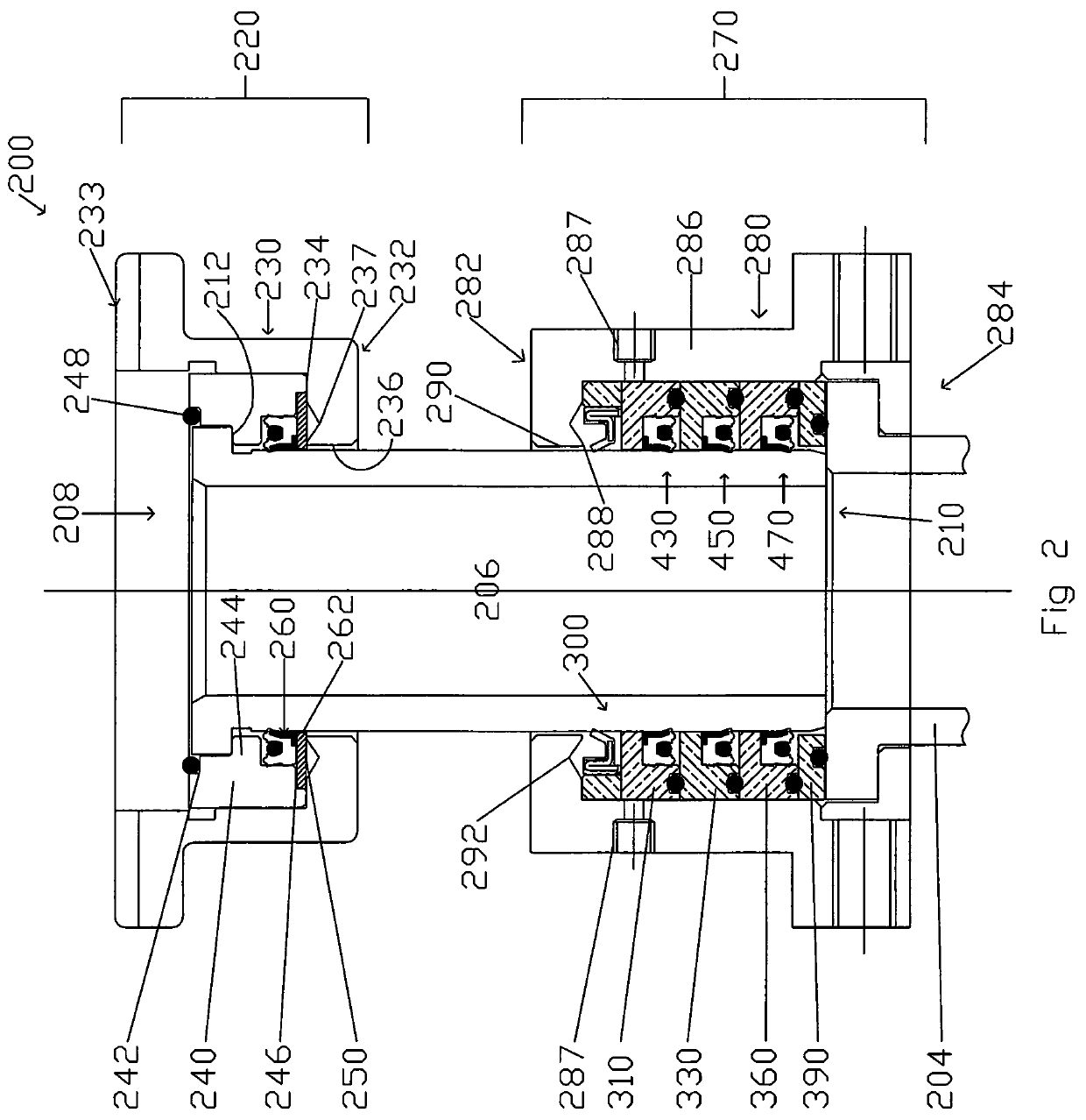
[0028]Referring now to FIG. 2, shown is high pressure seal assembly 200 of the invention. High pressure seal assembly 200 may be used for connection to an upper static connector pipe or gooseneck and a dynamic lower connector pipe or shaft 204. In one embodiment, high pressure seal assembly 200 includes washpipe 206 defining upper end 208 and lower end 210. Upper end 208 defines a flange 212 having a lower surface.

[0029]Static upper seal assembly is designated generally 220 and surrounds upper end 208 of washpipe 206. Static upper seal assembly 220 includes upper packing nut 230 that defines lower end 232 and upper end 233. Lower end 232 has an inside surface 234. Lower end 232 defines upper seal washpipe orifice 236 for receiving washpipe 206. Inside surface 234 defines annular recess 237.

[0030]Upper seal ring 240 is received within upper packing nut 230. Upper seal ring 240 has an upper surface defining annular seal receptacle 242. Upper seal ring 240 also defines interior protrus...


PUM


Abstract

A high pressure seal assembly for connection to an upper and lower connector pipe. The seal assembly includes a lower seal assembly surrounding a lower end of a rotating pipe, e.g., a washpipe. The lower seal assembly includes a first and second seal ring that define an annular space. The seal rings have a simple cross-section and are identical, thereby facilitating ease of manufacture and assembly. High pressure seals are received within annular spaces of the respective seal rings. The high pressure seals define inner surfaces that have a layer of self-lubricating polymer for engaging the rotating pipe. The high pressure seals define a pressure facing cavity that receives a high pressure ring that mitigates the spreading of the body of the high pressure seals due to pressure and that prevents the seal from extruding through an adjacent gap. An excluder seal prevents debris from entering the seal assembly.

Description

FIELD OF THE INVENTION[0001]The invention relates to high pressure seals. More particularly, the invention relates to high pressure seals for washpipes.BACKGROUND OF THE INVENTION[0002]In a drilling system, high pressure fluids are sent down the bore hole through a washpipe and a drill string, and ultimately to a drill motor at the bottom of the drill string. The fluid is supplied to the motor for driving cutting tools under very high pressure. A seal is necessary at the joint between the non-rotary upper connection assembly and the rotary lower connection assembly to prevent leakage of the drilling fluid to the outside. The joint is between the upper connection assembly, which includes a housing for the stator assembly, and the lower connection assembly, which includes the rotor assembly that is affixed to and rotates with the drill string. The rotor and housing are sometimes collectively referred to as a “cartridge.” The seal for this joint is referred to as a washpipe seal.[0003]...

Claims


Application Information

Patent Timeline
Patent Type & Authority Patents(United States)
IPC IPC(8): E21B21/02E21B33/04E21B33/00
CPCE21B33/0415E21B21/02E21B2033/005E21B2200/01
Inventor DU, LEI
Owner CLARK SEALS
Why Eureka
Try Eureka