Clamp device

a technology of clamping device and clamping arm, which is applied in the direction of positioning apparatus, metal-working machine components, manufacturing tools, etc., can solve the problems of complex clamping device, large size, and inability to apply uniform clamping force to plural types of workpieces having different width dimensions, so as to achieve reliable and stable clamping plural types, effectively suppressing interference between workpiece and clamp arm, and enhancing discharge direction of workpieces

Active Publication Date: 2020-02-04
SMC CORP
View PDF20 Cites 0 Cited by
  • Summary
  • Abstract
  • Description
  • Claims
  • Application Information

AI Technical Summary

Benefits of technology

[0010]The present invention has been made in consideration of such a problem. It is an object of the present invention to clamp plural types of workpieces having different widths reliably and stably while suppressing upsizing of the device with a simple structure. It is also possible to increase the degree of freedom of the supply direction and the discharge direction of the workpieces.
[0025]According to the present invention, it is possible to reliably and stably clamp plural types of workpieces having different width dimensions while suppressing upsizing of the device with a simple structure, and to increase the degree of freedom of the supply direction and discharge direction of the workpieces.

Problems solved by technology

Therefore, in the case where the clamp distance and the width dimension of the workpiece (the distance between the portions of the workpiece in contact with the gripping surface of each clamp arm) are different, it is not easy to apply a uniform clamping force to plural types of workpieces having different width dimensions.
However, because a plurality of clamp arms corresponding to the types of workpieces is required, the clamp device becomes complicated and large in size.

Method used


Image

  • Clamp device
  • Clamp device
  • Clamp device

Examples


Embodiment Construction

[0035]Preferred embodiments of the clamp device according to the present invention will be described below with reference to the accompanying drawings.

[0036]The clamp device 10 according to the present embodiment clamps workpieces W1 and W2 between a pair (plurality) of clamp arms 16a, 16b, and is applied to, for example, a welding process of an automatic assembly line of the machine industry or the like.

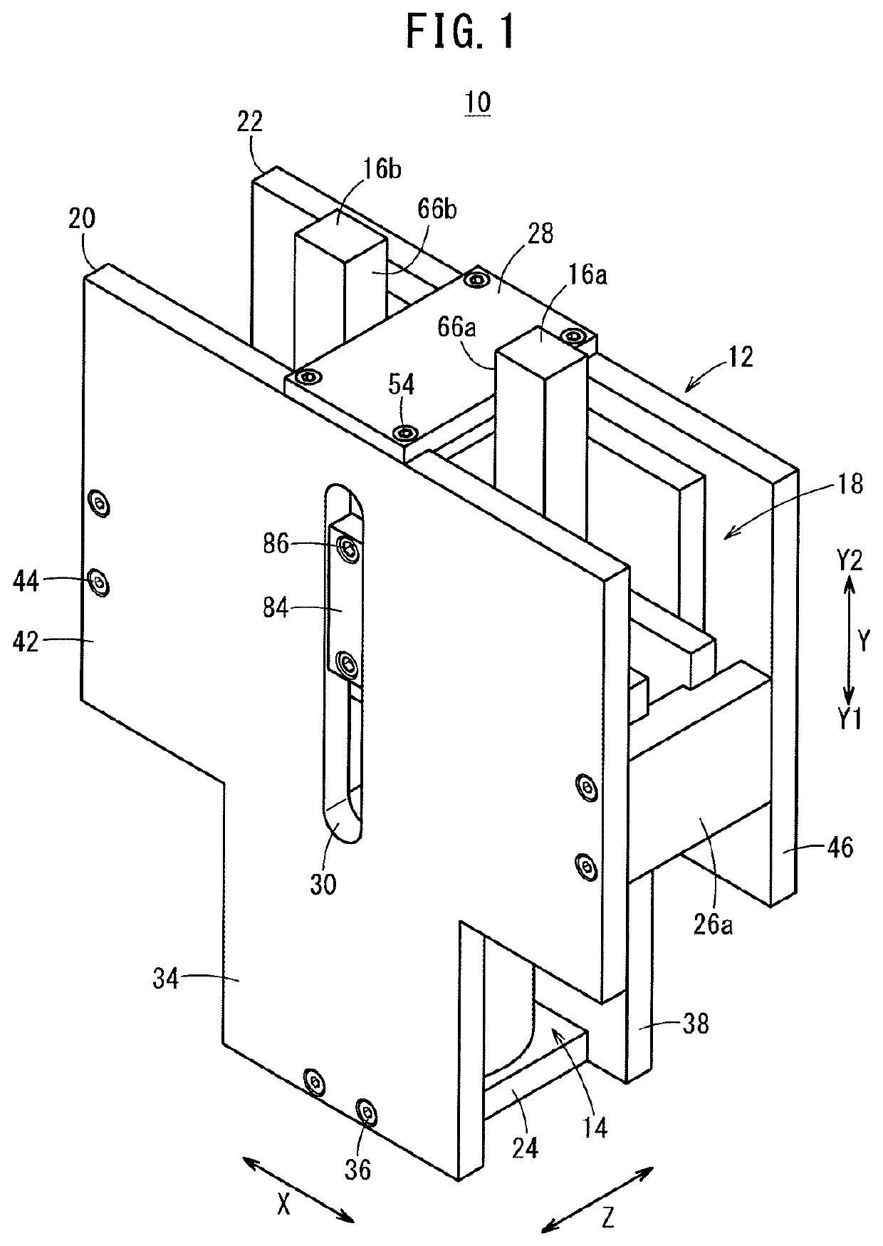
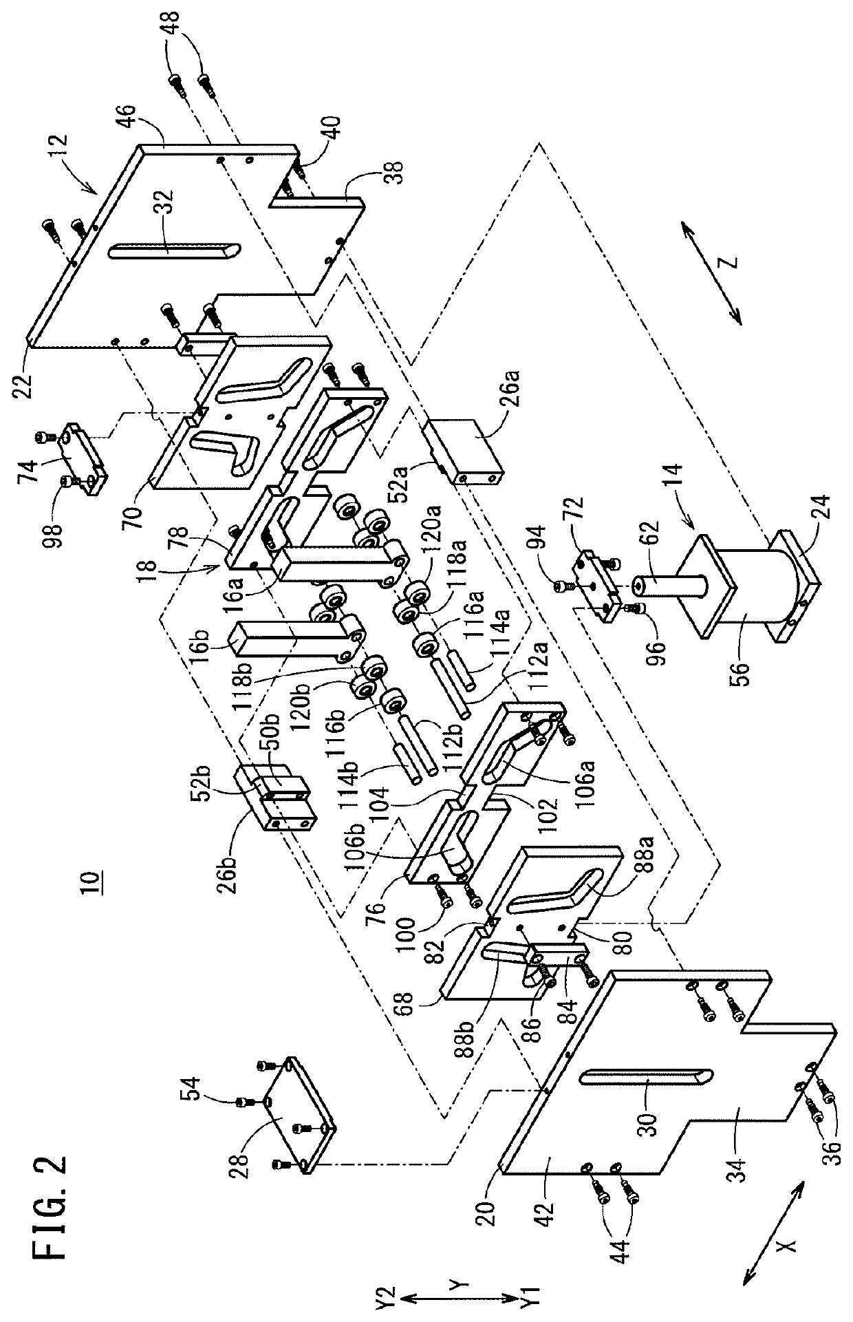
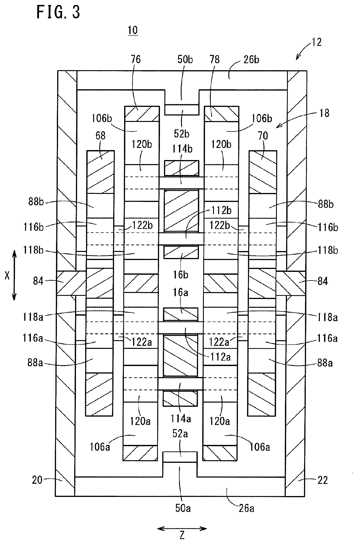
[0037]As shown in FIGS. 1 to 3, the clamp device 10 includes a clamp body 12, a driving unit 14 provided on the clamp body 12, a pair of right and left clamp arms 16a, 16b movably provided on the clamp body 12, and a driving force transmission mechanism 18 that transmits a driving force of the driving unit 14 to the respective clamp arms 16a, 16b.

[0038]In the following description, it is assumed that the width direction of the clamp device 10 (the direction in which the clamp arms 16a, 16b are arranged) is the X direction, the direction perpendicular to the X direction and the long...


PUM


Abstract

The present invention relates to a clamp device. The clamp device is provided with a driving force transmission mechanism, which transmits driving force from a drive unit to clamp arms. The driving force transmission mechanism converts the rectilinear movement of a piston rod of the drive unit into: a first operation, in which the clamp arms rotate while moving in directions toward or away from each other; and a second operation, in which the clamp arms move in parallel in directions toward or away from each other with gripping surfaces in a mutually parallel state.

Description

TECHNICAL FIELD[0001]The present invention relates to a clamp device for clamping a workpiece with a plurality of clamp arms.BACKGROUND ART[0002]The clamp device is widely used in a welding process of an automatic assembly line of the machine industry and the like. A clamp device of this type generally has a pair of clamp arms rotatably mounted on a clamp body via pins. By applying a driving force of a cylinder to one end portion of each clamp arm, these clamp arms are rotated about the pins, and a workpiece is clamped and positioned from the left and right sides by a gripping surface provided at the other end portion of each clamp arm. Then, the workpiece is subjected to necessary processing and a transportation process (see, for example, Japanese Patent No. 4950123).[0003]Among those clamp devices, for example, Japanese Laid-Open Patent Publication No. 2015-037829 discloses a clamp device in which a pair of clamp arms having attachments attached to the gripping surfaces and a pair...

Claims


Application Information

Patent Timeline
Patent Type & Authority Patents(United States)
IPC IPC(8): B23Q3/06
CPCB23Q3/06B25B5/064B25B5/087
Inventor FUKUI, CHIAKITAKAHASHI, KAZUYOSHISEO, TAKESHI
Owner SMC CORP
Why Eureka
Try Eureka