Power reception device, wearable device, and non-contact power feeding system

a power reception device and wearable technology, applied in the direction of dc-dc conversion, power electronics conversion, transportation and packaging, etc., can solve the problems of reducing transmission efficiency and fluctuation of resonance frequency of resonance circuit, and achieve the effect of suppressing the upsizing of the circuit and improving the transmission efficiency

Active Publication Date: 2021-08-24
DAIHEN CORP +1
View PDF16 Cites 0 Cited by
  • Summary
  • Abstract
  • Description
  • Claims
  • Application Information

AI Technical Summary

Benefits of technology

[0031]According to the present invention, it is possible to provide a power reception device, a wearable device, and a non-contact power feeding system that can improve the transmission efficiency while suppressing upsizing of the circuit.

Problems solved by technology

Alternatively, when, for example, a power reception device is installed in a flexible wearable device and the coil included in a resonance circuit is deformed, the inductance value fluctuates according to the deformation of the coil, consequently causing fluctuations of the resonance frequency of the resonance circuit.
Accordingly, a deviation also occurs between the resonance frequency of the resonance circuit of the power reception device and the frequency of the transmitted signal in this case, possibly reducing the transmission efficiency.

Method used


Image

  • Power reception device, wearable device, and non-contact power feeding system
  • Power reception device, wearable device, and non-contact power feeding system
  • Power reception device, wearable device, and non-contact power feeding system

Examples


embodiments

[0042]Embodiments of the present invention will be described with reference to the attached drawings. It should be noted here that components with identical reference numerals have identical or similar structures in the drawings.

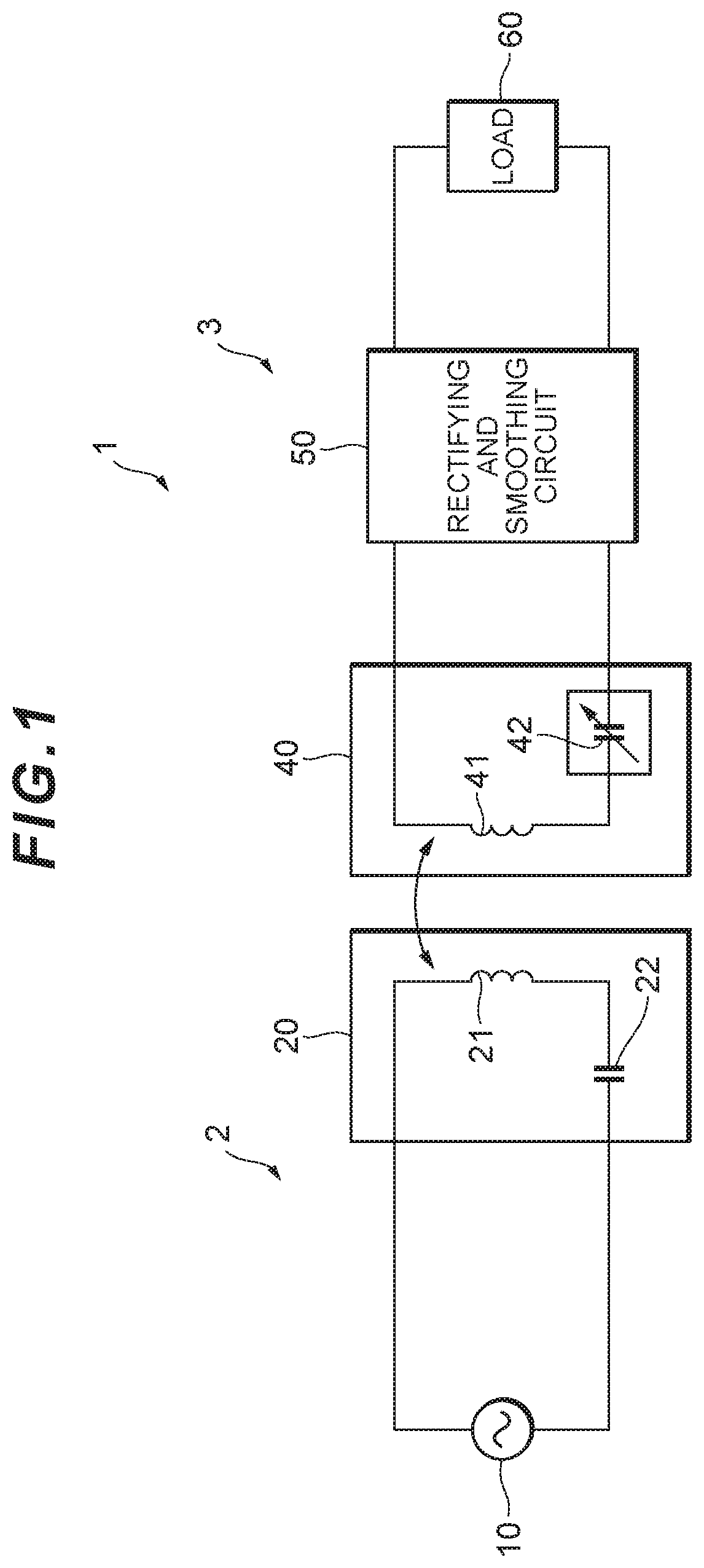
[0043]FIG. 1 is a diagram illustrating the entire structure of a non-contact power feeding system according to a first embodiment of the present invention. A non-contact power feeding system 1 illustrated in this drawing includes a power transmission device 2 that transmits electric power and a power reception device 3 that receives the electric power in a non-contact manner.

[0044]The power transmission device 2 includes, for example, a power supply circuit 10 and a power transmission unit 20.

[0045]A power supply circuit 10 generates and outputs an AC power supply voltage of a predetermined frequency (for example, approximately several kilohertz to several hundred megahertz). The AC power supply voltage is supplied to a power transmission unit 20.

[0046]The p...


PUM


Abstract

Provide are a power reception device, a wearable device, and a non-contact power feeding system that can improve the transmission efficiency while suppressing upsizing of the circuit thereof. A power reception device (3) includes a variable capacitance circuit (100) and a power reception coil (41) constituting a resonance circuit together with the variable capacitance circuit (100), in which the variable capacitance circuit (100) includes a first capacitor (C1) and a second capacitor (C2) connected in parallel to each other, a first switch (Tr1) connected in series to one end side of the first capacitor (C1), and a switch control circuit (110) that controls turning on and off of the first switch (Tr1) and includes a first comparator (OP1) that supplies a first control voltage to the first switch (Tr1) according to a comparison result between a reference voltage and an AC voltage applied to the second capacitor (C2).

Description

TECHNICAL FIELD[0001]The present invention relates to a power reception device, a wearable device, and a non-contact power feeding system.BACKGROUND ART[0002]In recent years, magnetic resonance technology attracts attention as one power feeding method for transmitting electric power from a power transmission device to a power reception device in a non-contact manner. In this magnetic resonance technology, the power transmission device and the power reception device have resonance circuits and electric power is transmitted via resonance phenomenon of these resonance circuits. Accordingly, electric power can be transmitted most efficiently when the resonance frequency of the resonance circuits of the power transmission device and the power reception device matches the frequency of a signal to be transmitted.[0003]The resonance frequency of a resonance circuit is a specific value defined by the element values of the coil and the capacitor included in the resonance circuit. Accordingly,...

Claims


Application Information

Patent Timeline
Patent Type & Authority Patents(United States)
IPC IPC(8): H02J50/12H02J50/70H02J7/02H02J7/34
CPCH02J50/12H02J7/02H02J7/345H02J50/70H02J2207/50H02J50/80H02M3/335H02M1/0058Y02B70/10H02M3/015H02M3/01
Inventor TSURUDA, YOSHINORINAKAMURA, SOUSUKEMIYAURA, TAKAHIRO
Owner DAIHEN CORP
Why Eureka
Try Eureka