
Arrays of tapered light-guides for snapshot spectral imaging

Active Publication Date: 2020-02-04
TKACZYK TOMASZ S
View PDF18 Cites 0 Cited by
  • Summary
  • Abstract
  • Description
  • Claims
  • Application Information

AI Technical Summary

Benefits of technology

The invention is about creating better ways to capture and analyze light in a way that allows for easier placement of optical elements. This is achieved by using tapered light-guides that create more space between them at the output of the array, which allows for the addition of optical elements as needed. The tapered guides make the input and output of the array the same size, but with more space in between them at the output. This allows for more efficient use of space and easier placement of optical elements.

Problems solved by technology

Imaging devices such as described in the Bodkin and Tkaczyk patents are limited in their applications by loss of light and the optical power and space requirements associated with the use of lenslets, pinholes or miniature mirrors.
In addition, these devices are complicated and expensive to manufacture.

Method used


Image

  • Arrays of tapered light-guides for snapshot spectral imaging
  • Arrays of tapered light-guides for snapshot spectral imaging
  • Arrays of tapered light-guides for snapshot spectral imaging

Examples


Embodiment Construction

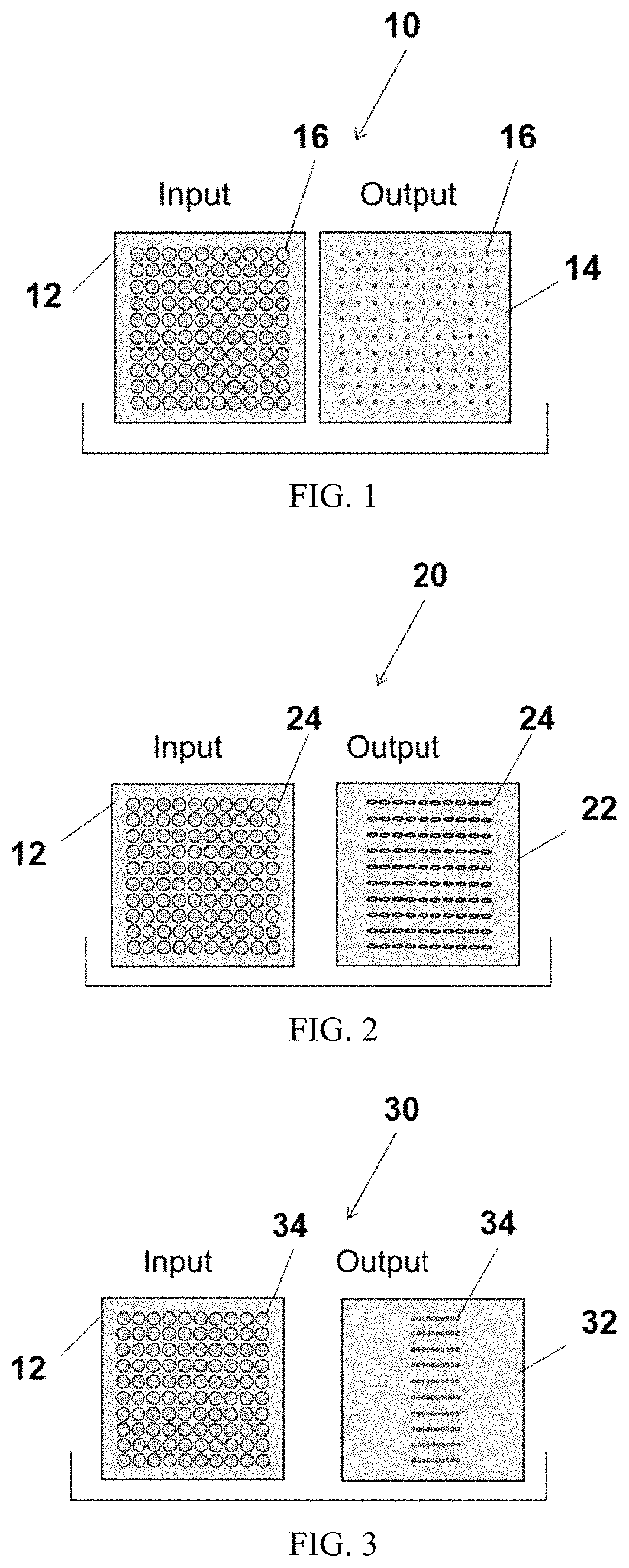
[0018]As used in this disclosure, “center distance” is intended to refer to the distance between the cross-section centers of adjacent light-guides. The term “array” is used to refer to the light-guide device propagating light between an input plane and an output plane as well as to the plurality of guides within the array. Though so represented for illustration, an array of light-guides is not necessarily structured in terms of linear rows and columns; rather, any bundle of guides is labeled as an array for the purposes of the invention. With regard to spectrum, the term “separation” and “separation unit” are used to indicate generally all approaches used in the art to identify various wavelengths and characteristics / parameters thereof.

[0019]Referring to the figures, wherein like parts are identified throughout by like numerals and symbols, FIG. 1 illustrates the most basic example of an array 10 according to the invention. The input plane 12 and the output plane 14 of the array ar...


PUM


Abstract

Arrays of tapered light-guides enable the development of snapshot multi-dimensional imaging systems, such as containing wavelength information in addition to spatial (x,y) image intensity-distribution information. As a result of the tapered guides, the input and output of the array can have the same overall dimension while producing greater total inter-guide free space at the output plane than present at the input plane for the introduction of optical elements, such as dispersers, as needed for particular applications. Individual guides may be tapered at different rates within the array and the array itself may be tapered as a whole.

Description

RELATED APPLICATIONS[0001]This application is based on and claims the priority of U.S. Provisional Application No. 62 / 072,588, filed Oct. 30, 2014, hereby incorporated by reference in its entirety.BACKGROUND OF THE INVENTIONField of the Invention[0002]The invention relates to optical light-guides and, in particular, to bundles of guides such as fibers and hollow reflective channels used in spectral imaging apparatus.Description of the Prior Art[0003]Optical fibers used in imaging devices are known in various configurations designed for particular applications. U.S. Pat. No. 3,786,840 (Courtney-Pratt et al.), for example, describes woven optical fibers that permit reproducible transformations between input and output fiber arrays. U.S. Pat. No. 6,851,844 (Guy) discloses a woven fiber fabric capable of emitting light in a directed manner. U.S. Pat. No. 8,174,694 (Bodkin), U.S. Pat. No. 8,233,148 (Bodkin) and U.S. Pat. No. 8,654,328 (Tkaczyk et al.) describe imaging systems where lensl...

Claims


Application Information

Patent Timeline
IPC IPC(8): G02B6/06G02B6/04G02B6/08H04N5/225G02B6/34
CPCG02B6/08G02B6/34H04N5/2254G02B6/06G01J3/0218G02B6/29388G02B6/29373G02B6/29311G01J3/0208G01J3/14G01J3/18G01J3/2823H04N23/55
Inventor TKACZYK, TOMASZ S.
Owner TKACZYK TOMASZ S
Features
  • Generate Ideas
  • Intellectual Property
  • Life Sciences
  • Materials
  • Tech Scout
  • Unparalleled Data Quality
  • Higher Quality Content
  • 60% Fewer Hallucinations
Learn More