LED socket assembly

Active Publication Date: 2011-06-09
TYCO ELECTRONICS LOGISTICS AG (CH)
View PDF56 Cites 47 Cited by
  • Summary
  • Abstract
  • Description
  • Claims
  • Application Information

AI Technical Summary

Benefits of technology

[0005]A need remains for a lighting system that may be efficiently packaged into a lighting fixture.

Problems solved by technology

These systems are not without disadvantages.
For instance, problems arise when the LEDs or the PCB needs to be replaced in the future.
The rework process is tedious and may require a skilled person

Method used


Image

  • LED socket assembly
  • LED socket assembly
  • LED socket assembly

Examples


Example

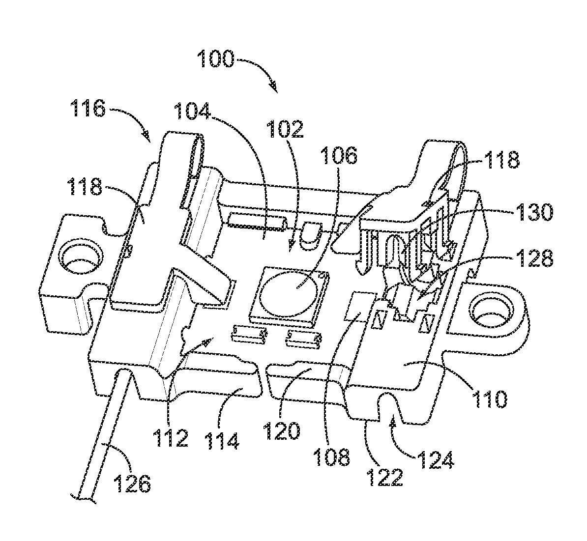
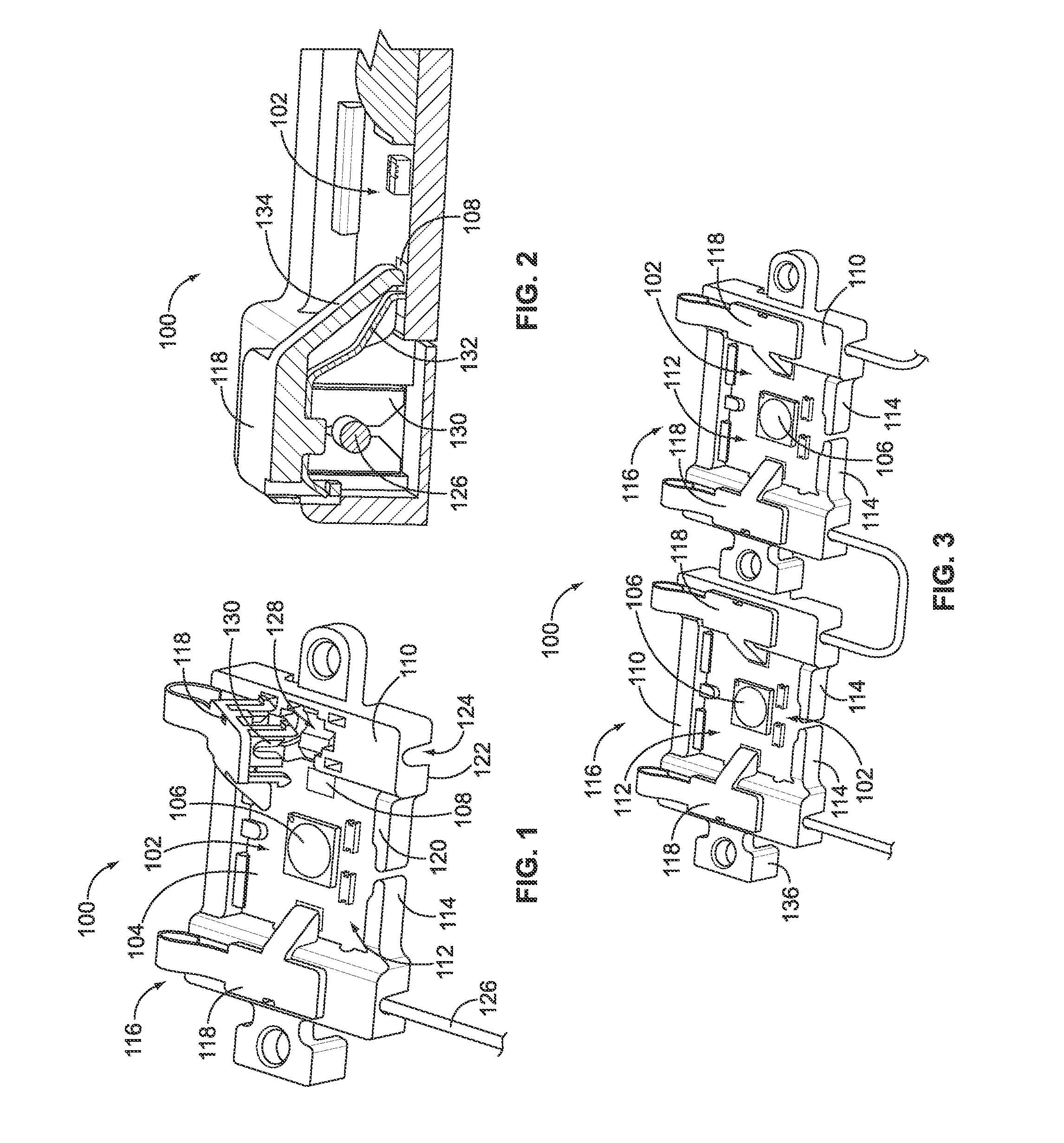
[0025]FIG. 1 is a top perspective view of a socket assembly 100 formed in accordance with an exemplary embodiment. The assembly 100 is part of a light engine that is used for residential, commercial or industrial use. The assembly 100 may be used for general purpose lighting, or alternatively, may have a customized application or end use.

[0026]The assembly 100 includes a light emitting diode (LED) package 102 having an LED printed circuit board (PCB) 104 with an LED 106 mounted thereto. In the illustrated embodiment, a single LED 106 is mounted to the LED PCB 104, however it is realized that any number of LEDs 106 may be mounted to the LED PCB 104. The LED PCB 104 may be sized appropriately depending on the number of LEDs 106 mounted thereto. The LED package 102 includes a plurality of power contacts 108 on the LED PCB 104. In the illustrated embodiment, the power contacts 108 are positioned proximate opposite edges of the LED PCB 104. Alternative arrangements of the power contacts ...


PUM


Abstract

A socket assembly includes a light emitting diode (LED) package having an LED printed circuit board (PCB) with an LED mounted thereto. The LED package has a power contact configured to receive power from a power source to power the LED. The socket assembly also includes a socket housing having a receptacle that removably receives the LED package. The socket housing has a securing feature engaging the LED PCB to secure the LED PCB within the receptacle, where the securing feature is configured to release the LED PCB to remove the LED PCB from the receptacle. Optionally, the socket housing may include mounting features configured to mount the socket housing to a base, where the LED package is removable from the socket housing while the socket housing remains mounted to the base. A second LED package may be provided, where the LED package is removable from the receptacle and is replaced by the second LED package.

Description

CROSS REFERENCE TO RELATED APPLICATIONS[0001]This application Relates to U.S. patent application titled SOLID STATE LIGHTING ASSEMBLY, having docket number CS-01137 (958-4047), U.S. patent application titled LED SOCKET ASSEMBLY, having docket number CS-01138 (958-4048), U.S. patent application titled SOLID STATE LIGHTING SYSTEM, having docket number CS-01139 (958-4049), and U.S. patent application titled SOCKET ASSEMBLY WITH A THERMAL MANAGEMENT STRUCTURE, having docket number CS-01141 (958-4051) each filed concurrently herewith, the subject matter of each of which are herein incorporated by reference in their entirety.BACKGROUND OF THE INVENTION[0002]The subject matter herein relates generally to solid state lighting assemblies, and more particularly, to LED socket assemblies.[0003]Solid-state light lighting systems use solid state light sources, such as light emitting diodes (LEDs), and are being used to replace other lighting systems that use other types of light sources, such as...

Claims


Application Information

Patent Timeline
IPC IPC(8): H01R13/514
CPCF21K9/00F21V19/003F21V19/004H01R4/2433F21V23/06F21Y2115/10H01R13/115H01R33/06H01R33/0827
Inventor MOSTOLLER, MATTHEW EDWARDDAILY, CHRISTOPHER GEORGEGINGRICH, III, CHARLES RAYMONDWEBER, RONALD MARTIN
Owner TYCO ELECTRONICS LOGISTICS AG (CH)
Why Eureka
Try Eureka