
Lidar system with improved signal-to-noise ratio in the presence of solar background noise

a technology of solar background noise and signal-to-noise ratio, which is applied in the field of lidar systems, can solve problems such as false-positive detections and corrupt measurements of lidar systems

Active Publication Date: 2020-02-11
LUMINAR TECH INC
View PDF136 Cites 13 Cited by
  • Summary
  • Abstract
  • Description
  • Claims
  • Application Information

AI Technical Summary

Benefits of technology

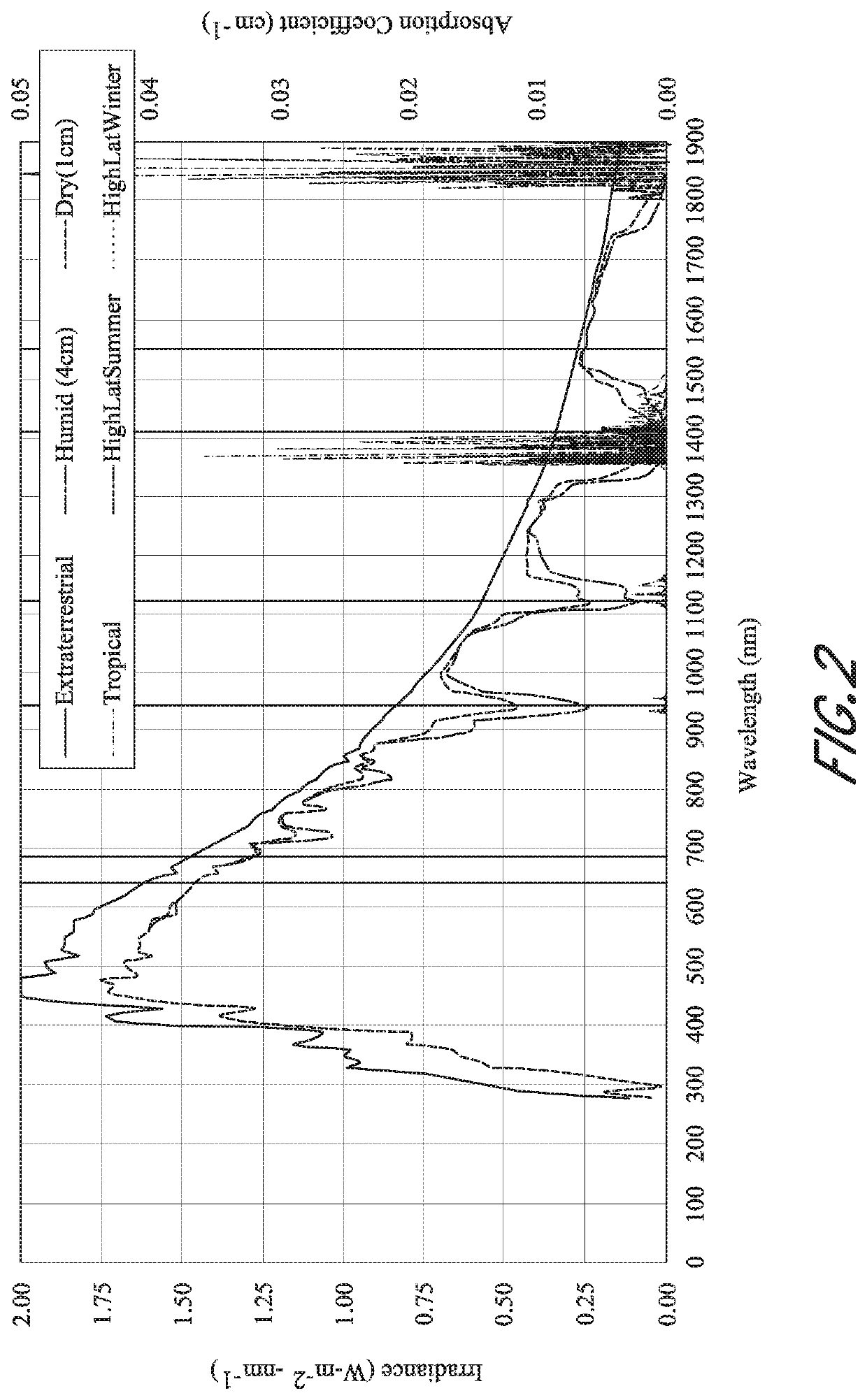
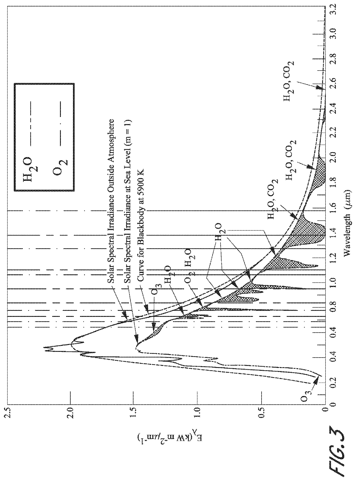
This approach significantly improves the signal-to-noise ratio, especially for short operating ranges, by leveraging strong atmospheric absorption to lower the noise floor from solar radiation, while maintaining eye-safe power levels.

Problems solved by technology

Therefore, light from the sun can act as background noise which can obscure signal light detected by the lidar system.
This solar background noise can result in false-positive detections or can otherwise corrupt measurements of lidar systems.

Method used


Image

  • Lidar system with improved signal-to-noise ratio in the presence of solar background noise
  • Lidar system with improved signal-to-noise ratio in the presence of solar background noise
  • Lidar system with improved signal-to-noise ratio in the presence of solar background noise

Examples


Embodiment Construction

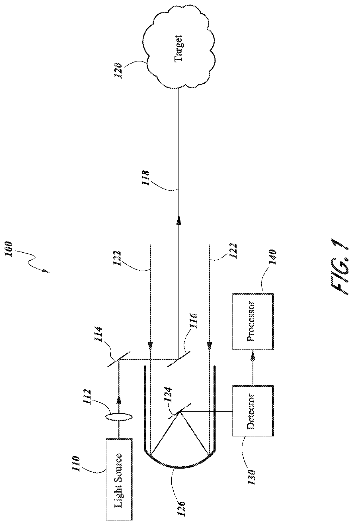
[0020]FIG. 1 is a schematic illustration of an example lidar system 100. The lidar system 100 includes a light source 110. The light source 110 can be, for example, a laser which emits light having a particular operating wavelength. The light source 110 emits an output beam of light 118 which is directed downrange toward a remote target 120. The output beam of light 118 can be continuous-wave, pulsed, or modulated in any way desired for a given application.

[0021]The lidar system 100 can optionally include one or more optical components to condition the output beam 118. These can include, for example, a beam expander lens 112 to expand the output beam 118 to a desired diameter. The lidar system 100 can also include one or more mirrors to direct the output beam 118 along a desired path. For example, a first mirror 114 directs the output beam 118 towards a second mirror 116. In some embodiments, the first and / or second mirrors 114, 116 are scanning mirrors which can steer the output be...


PUM


Abstract

A lidar system with improved signal-to-noise ratio in the presence of solar background noise. The lidar system can comprise a light source to emit light toward a target. The light source can have an operating wavelength which lies within a band that delineates a relative maximum in atmospheric absorption. The lidar system can also include a detector to detect scattered light from the target and a processor to determine a characteristic of the target based on a characteristic of the scattered light received at the detector.

Description

[0001]INCORPORATION BY REFERENCE TO ANY PRIORITY APPLICATIONS[0002]Any and all applications for which a foreign or domestic priority claim is identified in the Application Data Sheet as filed with the present application are hereby incorporated by reference under 37 CFR 1.57. For example, this application claims priority to U.S. Provisional Patent Application No. 62 / 243,633, filed Oct. 19, 2015, and entitled “LIDAR SYSTEM WITH IMPROVED SIGNAL-TO-NOISE RATIO IN THE PRESENCE OF SOLAR BACKGROUND NOISE,” the entirety of which is hereby incorporated by reference herein.BACKGROUNDField[0003]This disclosure relates to lidar systems. More particularly, this disclosure relates to lidar systems having improved signal-to-noise ratio in the presence of solar background noise.Description of the Related Art[0004]Lidar is a technology that can be used to measure distances to remote targets. Typically, a lidar system includes a light source and a detector. The light source can be, for example, a la...

Claims


Application Information

Patent Timeline
Patent Type & Authority Patents(United States)
IPC IPC(8): G01S17/10G01S17/88G01S7/497G01S7/487G01S7/481G01S17/08G01S17/26
CPCG01S17/88G01S7/4815G01S17/26G01S7/4814G01S7/4876G01S7/497G01S17/08G01S7/4816
Inventor CAMPBELL, SCOTT R.EICHENHOLZ, JASON M.WEED, MATTHEW D.
Owner LUMINAR TECH INC
Learn More